SUPPLEMENTAL RESTRAINTS
Supplemental Restraints Wiring Diagram for Hummer H2 2007
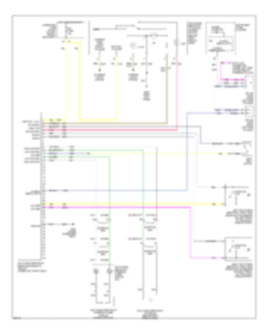
List of elements for Supplemental Restraints Wiring Diagram for Hummer H2 2007:
- Air bag indicator
- Class 2 serial data
- Data link connector (under left side of dash below steering column)
- Exterior lights system
- G203 (right kick panel)
- G304 (under passenger seat)
- Ground
- High control
- Hot in run or start
- Ign
- Ignition 1 volt
- Ignition 1 voltage
- Illum
- Ind control
- Inflatable restraint i/p module (behind right side of dash)
- Inflatable restraint i/p module disable switch (behind right side of dash)
- Inflatable restraint sensing/diagnostic module (under left front seat)
- Inflatable restraint steering wheel module (under horn pad)
- Inflatable restraint steering wheel module coil
- Instrument panel cluster
- Interior lights system
- L belt sw
- Left inflatable restraint front end discriminating sensor (on left front of vehicle by core support)
- Logic
- Low control
- Low ref
- Nca
- Off
- Pnk
- Right inflatable restraint front end discriminating sensor (on right front of vehicle by core support)
- Seat belt switch
- Shorting bar
- Shorting clip
- Signal
- Sir fuse 15a
- Splice pack sp205 (left side of dash)
- Splice pack sp207 (left side of dash)
- Sw signal
- Tan/
- Underhood fuse block (on left side of eng compt)
 English