SUPPLEMENTAL RESTRAINTS
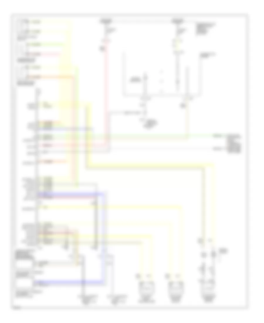
Supplemental Restraint Wiring Diagram for Infiniti G20 2002
List of elements for Supplemental Restraint Wiring Diagram for Infiniti G20 2002:
- (at base of left "b" pillar) b6
- (at base of right "b" pillar) b25
- (behind left kick panel) m15
- Air bag diagnosis sensor unit (below rear of center console)
- Air bag indicator
- Air bag w/l
- B19
- B33
- Combination meter
- Connector (dlc) (partial) (under left dash panel, near fuse box cover)
- Data link
- Driver side air bag module
- Fuse 11 10a
- Fuse 22 10a
- Fuse block (j/b) (behind dash, left of steering column)
- Ground
- Hot in on or start
- Ignition
- Left lock +
- Left lock -
- Left satellite sensor (at base of left "b " pillar)
- Left seat belt pretensioner
- Left side air bag module
- M39
- M40
- Nca
- Passenger side air bag module
- Right lock +
- Right lock -
- Right satellite sensor (at base of right "b " pillar)
- Right seat belt pretensioner
- Right side air bag module
- Sat lh +
- Sat lh -
- Sat rh +
- Sat rh -
- Spiral cable
- Sq as +
- Sq as -
- Sq dr +
- Sq dr -
- Sq pas +
- Sq pas -
- Sq pdr +
- Sq pdr -
- Sq side lh +
- Sq side lh -
- Sq side rh +
- Sq side rh -
 English