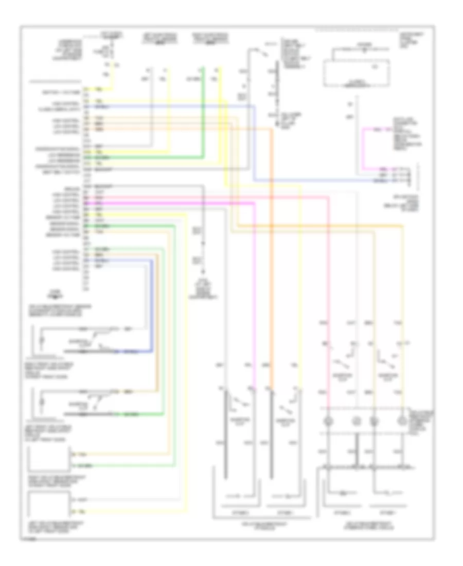
SUPPLEMENTAL RESTRAINTS
Supplemental Restraints Wiring Diagram for Isuzu Ascender 2003
List of elements for Supplemental Restraints Wiring Diagram for Isuzu Ascender 2003:
- (on lower left "b" pillar) g302
- 12v
- A10
- A11
- A12
- A13
- A14
- A15
- A16
- A17
- A18
- Air bag
- B10
- C1 a1
- Case ground
- Class 2 serial data
- Data link connector (dlc) (partial) (below dash, above accelerator pedal)
- Discriminating signal
- Driver seat belt buckle switch (in seat belt buckle assembly)
- G102 (at left side of engine compartment)
- Ground
- High control
- Hot in run & start
- Ignition 1 voltage
- Inflatable restraint i/p module
- Inflatable restraint sensing & diagnostic module (sdm) (beneath lower console)
- Inflatable restraint steering wheel module
- Inflatable restraint steering wheel module coil
- Instrument panel cluster (ipc)
- Left electronic frontal sensor (efs)
- Left front inflatable restraint side impact module (in left front door)
- Left inflatable restraint side impact sensor (sis) (in left front door)
- Low control
- Low reference
- Nca
- Pnk
- Right electronic frontal sensor (efs)
- Right front inflatable restraint side impact module (in right front door)
- Right inflatable restraint side impact sensor (sis) (in right front door)
- Seat belt switch
- Sensor signal
- Sensor voltage
- Shorting clip
- Sir fuse 18 10a
- Splice pack sp205 (below left side of dash)
- Stage 1
- Stage 2
- Tan
- Underhood fuse block (on left side of engine compartment)
 English