SUPPLEMENTAL RESTRAINTS
Supplemental Restraints Wiring Diagram for Isuzu Axiom 2004
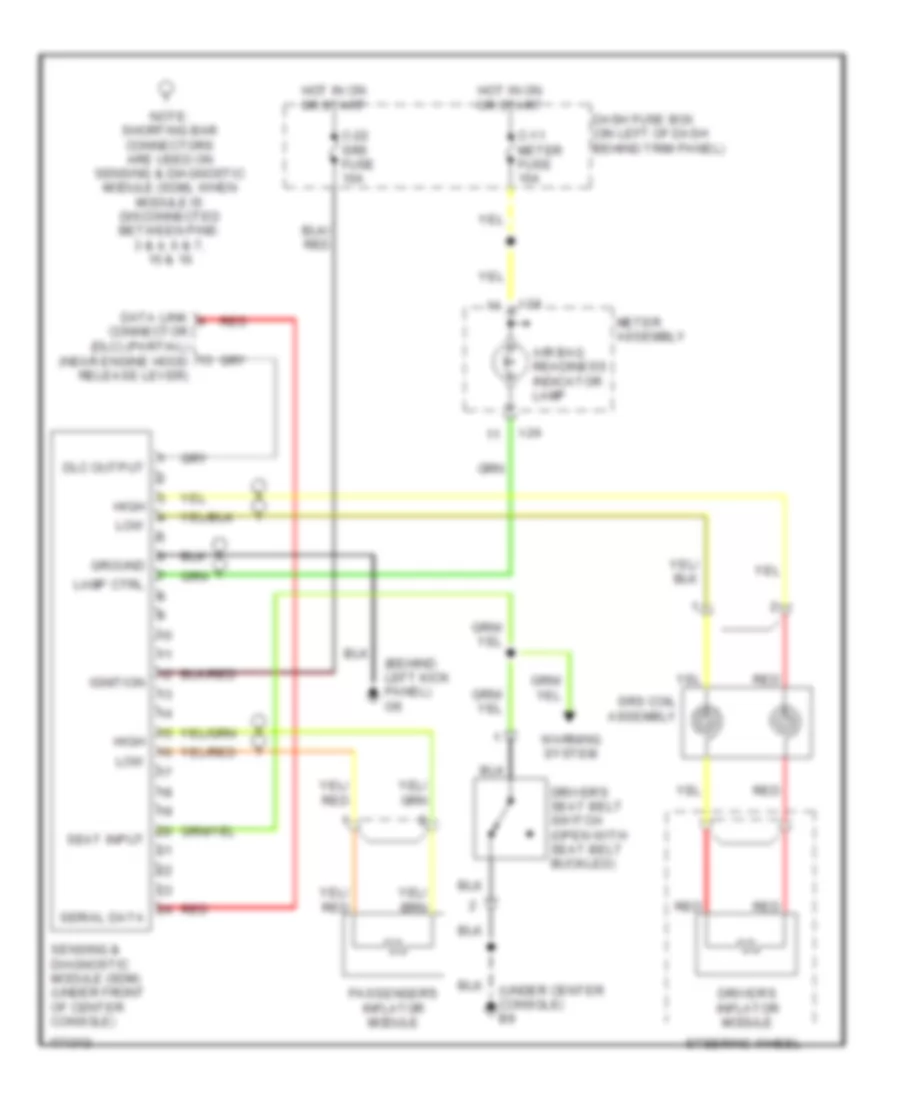
List of elements for Supplemental Restraints Wiring Diagram for Isuzu Axiom 2004:
- (behind left kick panel) i36
- (under center console) b9
- Air bag readiness indicator lamp
- C-11 meter fuse 15a
- C-22 srs fuse 10a
- Dash fuse box (on left of dash behind trim panel)
- Data link connector (dlc) (partial) (near engine hood release lever)
- Dlc output
- Driver's inflator module
- Driver's seat belt switch (open with seat belt buckled)
- Ground
- High
- Hot in on or start
- I-24
- Ignition
- Lamp ctrl
- Low
- Meter assembly
- Note: shorting bar connectors are used on sensing & diagnostic module (sdm), when module is disconnected between pins: 3 & 4, 6 & 7, 15 & 16
- Passenger's inflator module
- Red
- Seat input
- Sensing & diagnostic module (sdm) (under front of center console)
- Serial data
- Srs coil assembly
- Steering wheel
- Warning system
 English