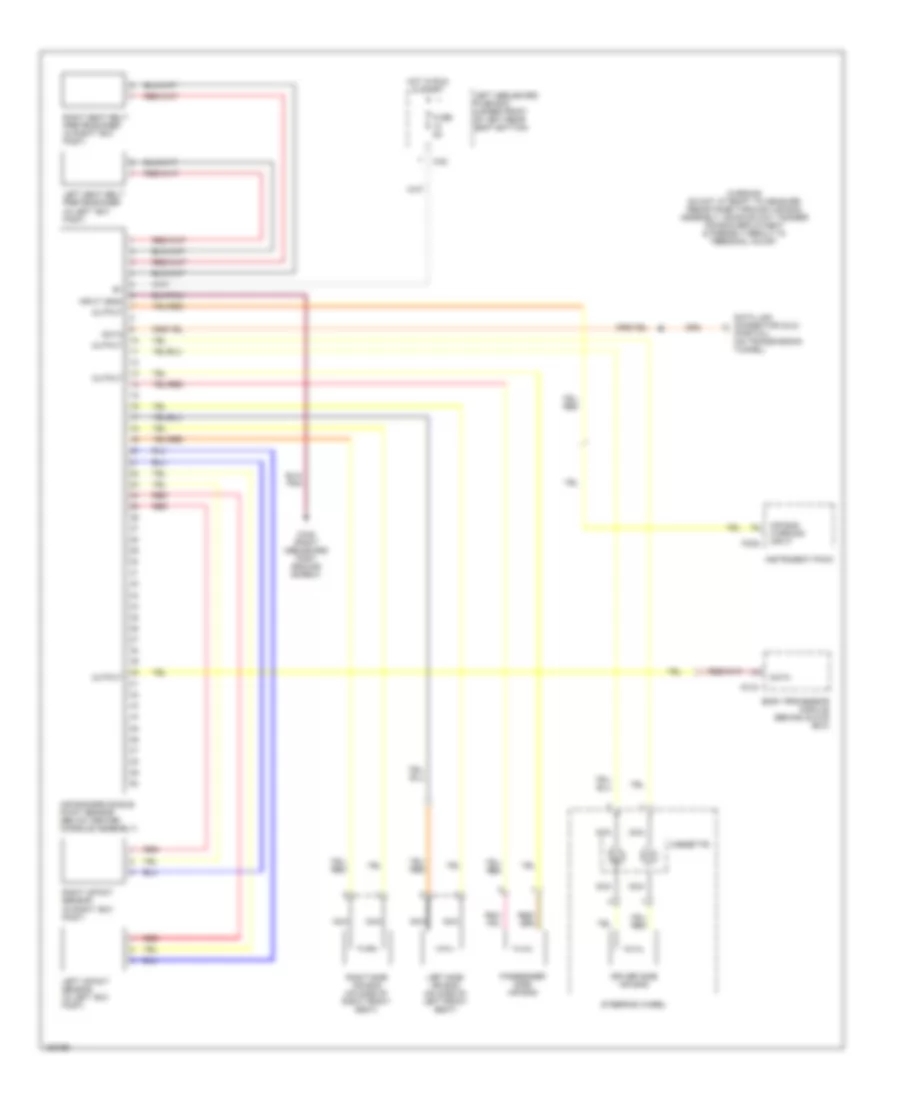
SUPPLEMENTAL RESTRAINTS
Supplemental Restraints Wiring Diagram for Jaguar XJR 2003
List of elements for Supplemental Restraints Wiring Diagram for Jaguar XJR 2003:
- (partial) (on transmission tunnel)
- Air bag warning input
- Air bag/srs single point sensor (below center console assembly)
- Body processor module (behind glove box)
- Ca2
- Ca48 (right heelboard post ground screw)
- Cassette
- Data
- Data link connector (dlc)
- Driver side air bag
- Fc15
- Fc25
- Fuse 5a
- Hot in run & start
- Input (gnd)
- Instrument pack
- Left heelboard fuse box (under front of left rear seat bottom)
- Left impact sensor (in left "b/c" post)
- Left seat belt pretensioner (in left "b/c" post)
- Left side air bag (on side of left front seat)
- Nca
- Output
- Passenger side air bag
- Red
- Right impact sensor (in right "b/c" post)
- Right seat belt pretensioner (in right "b/c" post)
- Right side air bag (on side of right front seat)
- Steering wheel
- Warning do not attempt to measure resistance through air bag assembly, doing so may trigger air bag deployment & possibly result in personal injury
 English