SUPPLEMENTAL RESTRAINTS
Supplemental Restraints Wiring Diagram for Lincoln Blackwood 2003
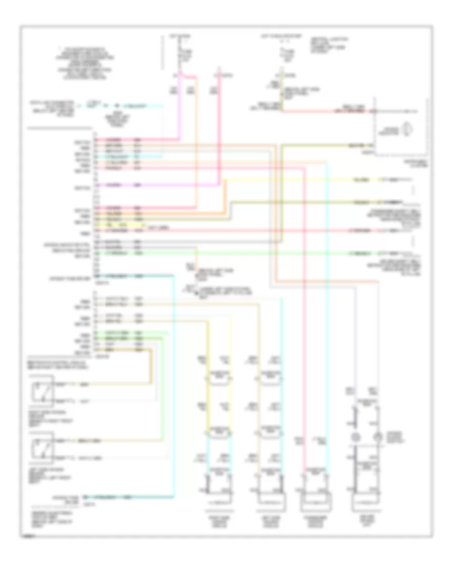
List of elements for Supplemental Restraints Wiring Diagram for Lincoln Blackwood 2003:
- (behind left side dash panel) s237
- (not used)
- (under left side of dash, at base of left "a" pillar) g201
- Air bag indicator
- Air bag indicator ctrl
- Air bag sliding contact
- Air bag tone driver
- C201a
- C2041a
- C2041b
- C220a
- C270a
- C270b
- Central junction box (cjb) (under left side of dash)
- Data link connector (dlc) (partial) (below left center of dash)
- Dedicated ground
- Driver air bag unit
- Driver safety belt retractor pretensioner (near base of left "b" pillar)
- Feed
- Fuse f2.22 10a
- Fuse f2.30 30a
- Generic electronic module (gem) (behind left side of dash)
- Hot in run
- Hot in run or start
- Ignition
- Instrument cluster
- Iso bus
- Left side air bag module
- Left side air bag sensor (beneath left front seat)
- Nca
- Passenger air bag module
- Passenger safety belt retractor pretensioner (near base of right "b" pillar)
- Pin shorting bar is engaged when module connector is disconnected from harness (shorting bar is connected between pins: 20-21 conn. c2041a 2-3 & 5-6 conn. c2041b)
- Restraints control module (behind right center of dash)
- Return
- Right side air bag module
- Right side air bag sensor (beneath right front seat)
- S229 (behind left side dash panel)
- Shorting bar
 English