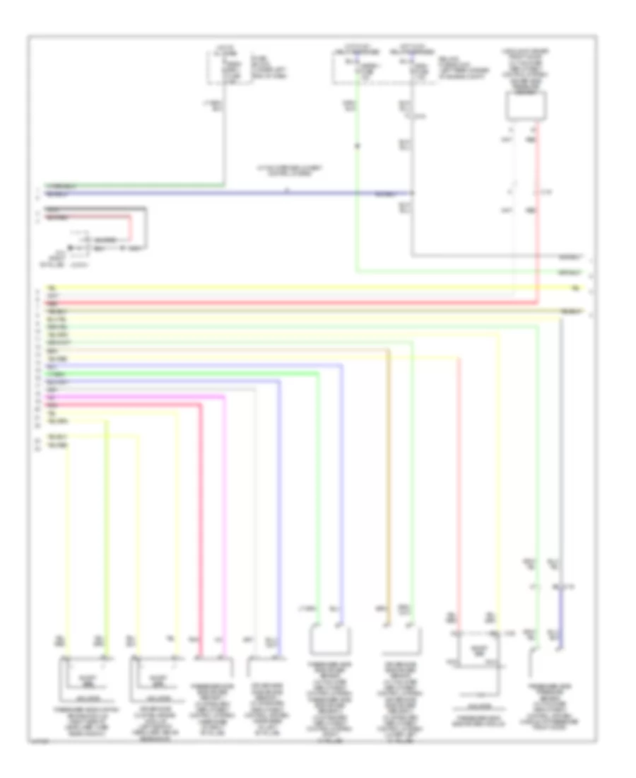
SUPPLEMENTAL RESTRAINTS
Supplemental Restraints Wiring Diagram (1 of 3) for Mazda 6 Sport 2014

List of elements for Supplemental Restraints Wiring Diagram (1 of 3) for Mazda 6 Sport 2014:
- (under front passenger's seat) (w/ two step deployment control system) seat weight sensor control module
- 0810-101a
- 0810-101b
- 0810-120a
- 0810-120b
- 2aa
- 2ab
- 2ac
- 2ad
- 2n c-04
- C-19
- C-20
- Driver-side buckle switch (in driver's seat belt buckle assembly)
- Driver-side lap pre-tensioner seat belt (w/ two step deployment control system) (base of left "b" pillar)
- Driver-side pre-tensioner seat belt (base of left "b" pillar)
- G14 (right "b" pillar)
- Inflator
- J/c g14
- Left front seat weight sensor (under left front passenger seat)
- Left rear seat weight sensor (under left rear of front passenger seat)
- Nca
- Passenger-side crash zone sensor (w/ two step deployment control system) (right front of engine compt)
- Passenger-side lap pre-tensioner seat belt (w/ two step deployment control system) (base of right "b" pillar)
- Passenger-side pre-tensioner seat belt (base of right "b" pillar)
- Pnk
- Red
- Right front seat weight sensor (under right front passenger seat)
- Right rear seat weight sensor (under right rear of front passenger seat)
- Sas control module (under rear of center console)
- Short bar
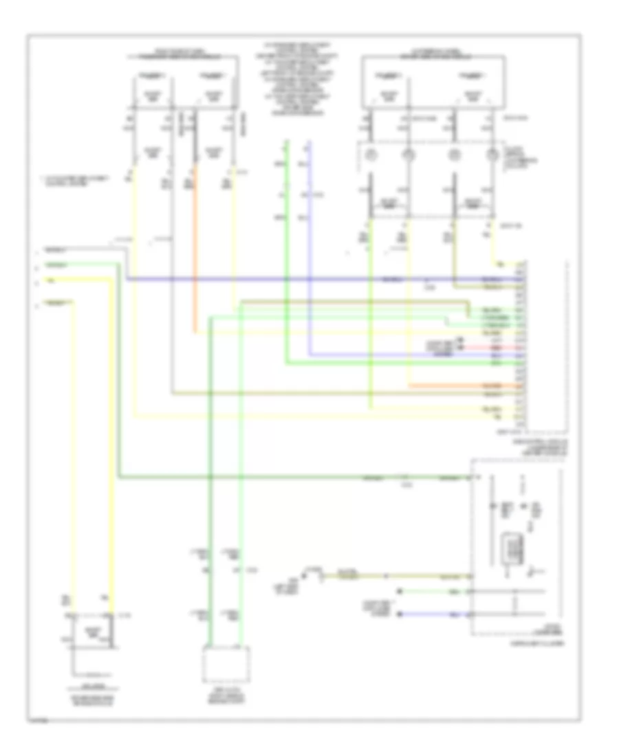
Supplemental Restraints Wiring Diagram (2 of 3) for Mazda 6 Sport 2014
List of elements for Supplemental Restraints Wiring Diagram (2 of 3) for Mazda 6 Sport 2014:
- (middle of driver front door) (w/ two-step deployment control system) driver-side pressure sensor
- 1f c-04
- Ae c-16
- C-20
- Driver-side curtain air bag module (left side of headliner, above rear door)
- Driver-side side air bag sensor (w/ two step deployment control system) driver-side side air bag sensor 2 (w/ standard deployment control system) (lower left "c" pillar)
- Driver-side side air bag sensor 1 (w/ standard deployment control system) (near base of left "b" pillar)
- Fuse block (under left end of dash)
- G14 (right "b" pillar) j/c g14
- Hot at all times
- Hot w/ ig1 relay energized
- Inflator
- J c-15
- Meter 1 fuse 10a
- Nca
- Passenger-side curtain air bag module (right side of headliner, over rear window)
- Passenger-side pressure sensor (w/ two step deployment control system) (middle of passenger front door)
- Passenger-side side air bag module
- Passenger-side side air bag sensor (w/ two step deployment control system) passenger-side side air bag sensor 2 (w/ standard deployment control system) (right "c" pillar)
- Passenger-side side air bag sensor 1 (w/ standard deployment control system) (near base of right "b" pillar)
- Pnk
- Red
- Relay & fuse block (left rear corner of engine compt)
- Short bar
- Srs1 fuse 7.5a
- Srs2/ escl fuse 15a
- W/ two step deployment control system
Supplemental Restraints Wiring Diagram (3 of 3) for Mazda 6 Sport 2014
List of elements for Supplemental Restraints Wiring Diagram (3 of 3) for Mazda 6 Sport 2014:
- (in steering wheel) driver-side air bag module
- (right side of dash) passenger-side air bag module
- (w/ standard deployment control system: center front of engine compt) (w/ two-step deployment control system: left front of engine compt) (w/ standard deployment control system) crash zone sensor (w/ two step deployment control system) driver-side crash zone sensor
- 0810-101c
- 0810-103
- 0810-104a
- 0810-104b 2a
- 0810-105a
- 0810-105b
- 2n c-03
- Air bag ind
- C-03
- C-09
- C-13 c
- C-19
- Clock spring (in steering column)
- Computer data lines system
- Control system
- Detection failure circuit
- Driver-side side air bag module
- Dsc hu/cm (right side of engine compt)
- G09 (left side of dash)
- Inflator
- Inflator 1
- Inflator 2
- Instrument cluster
- J/c g09
- Micro- computer
- Nca
- Red
- Sas control module (under rear of center console)
- Seat belt ind
- Short bar
- W/ two step deployment