SUPPLEMENTAL RESTRAINTS
Supplemental Restraints Wiring Diagram for Mazda B3000 Dual Sport 2005
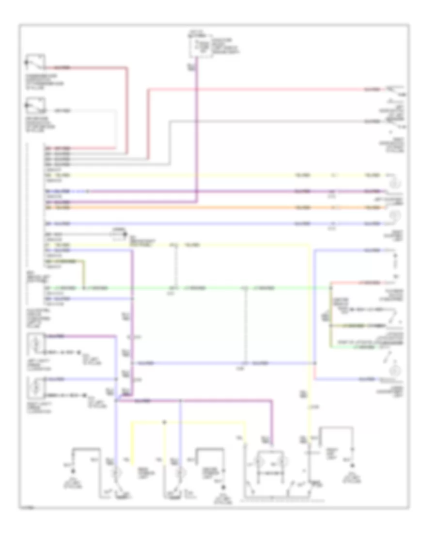
List of elements for Supplemental Restraints Wiring Diagram for Mazda B3000 Dual Sport 2005:
- (center rear of roof)
- 0914-101b
- 0914-101c
- 0940-01b
- 0940-01d
- 0940-01e
- 0940-01f
- 0940-01g
- Bcm (behind left kick panel)
- C-12
- C-13
- C-21
- C-21 e
- C-26
- C-28
- Cargo compartment light
- Center interior light
- Door
- Driver side door switch (at driver side "b" pillar)
- Front map light
- G01 (behind right kick panel)
- G14 (at left "d" pillar)
- G15
- Hot at all times
- J/c-g01
- Left courtesy light
- Left door switch (at left "c" pillar)
- Left vanity mirror illumination
- Liftgate latch switch (part of liftgate lock actuator)
- Main fuse block (left side of engine compt)
- Nca
- Off
- Passenger side door switch (at passenger side "b" pillar)
- Plg control module (if equipped) (left "d" pillar)
- Plg rear switch (if equipped)
- Rear interior light
- Right courtesy light
- Right door switch (at right "c" pillar)
- Right vanity mirror illumination
- Room fuse 15a
 Русский