
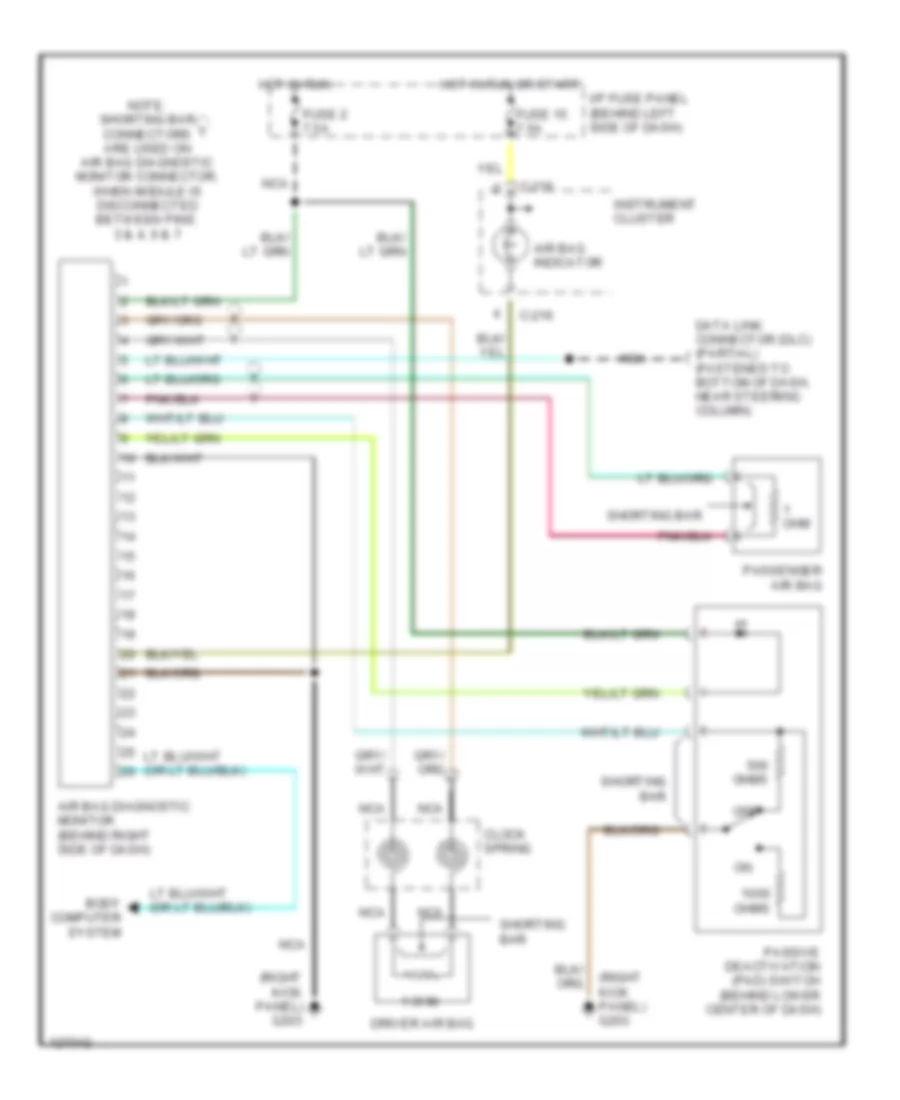
SUPPLEMENTAL RESTRAINTS
Supplemental Restraint Wiring Diagram for Mazda B4000 SE 2000
List of elements for Supplemental Restraint Wiring Diagram for Mazda B4000 SE 2000:
AIR CONDITIONINGANTI-LOCK BRAKESANTI-THEFTCOMPUTER DATA LINESENGINE PERFORMANCEBODY COMPUTERGROUND DISTRIBUTIONEXTERIOR LIGHTSCRUISE CONTROLINSTRUMENT CLUSTERHEADLIGHTSHORNPOWER DISTRIBUTIONINTERIOR LIGHTSPOWER DOOR LOCKSPOWER WINDOWSSUPPLEMENTAL RESTRAINTSRADIOSHIFT INTERLOCKSPOWER MIRRORSTRANSMISSIONWARNING SYSTEMSSTARTING/CHARGINGWIPER/WASHER