SUPPLEMENTAL RESTRAINTS
Supplemental Restraint Wiring Diagram for Mercury Mountaineer 2001
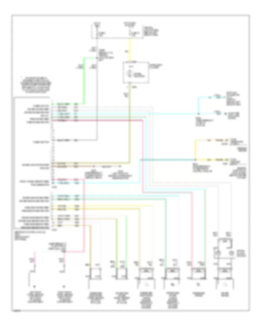
List of elements for Supplemental Restraint Wiring Diagram for Mercury Mountaineer 2001:
- (near breakout to central junction box) s217
- (near breakout to left front park/turn lamp) s131
- (partial) (behind left side of dash)
- Air bag indicator
- Air bag indicator driver
- Air bag sliding contact
- C2009
- C232
- C233
- C280
- C288
- Central junction box (behind left side of dash)
- Computer data lines system
- Data link connector (dlc)
- Driver air bag
- Driver air bag feed
- Driver air bag return
- Driver side air bag (w/side air bags) resistor a (w/o side air bags)
- Driver side air bag crash sensor (on left "b" pillar)
- Driver side air bag feed
- Driver side air bag return
- Driver side sensor feed
- Driver side sensor return
- Front crash sensor feed
- Fuse 15 7.5a
- Fuse 2 7.5a
- Fused ignition
- G108 (left front of engine compartment, near radiator)
- Generic electronic module (gem) (behind center of dash)
- Ground
- Hot in run
- Hot in run or start
- Instrument cluster
- Iso 9141
- Left front crash sensor (left front of engine compartment)
- Message center
- Nca
- Pass air bag feed
- Pass air bag return
- Pass side air bag feed
- Pass side air bag return
- Pass side sensor feed
- Pass side sensor return
- Passenger air bag
- Passenger side air bag (w/side air bags) resistor b (w/o side air bags)
- Passenger side air bag crash sensor (on right "b" pillar)
- Pin shorting bar is engaged when module connector is disconncted: (shorting bar connected between following pins: 3-4, 6-7 & 20-21 conn c232 2-3 & 5-6 conn c233)
- Restraint control module (rcm) (behind right kick panel)
- Right front crash sensor (right front of engine compartment)
- S216 (near breakout to restraints control module)
- S232 (near breakout to rear window defrost relay)
- S255 (near breakout to relay module)
- Shorting bar
- Tone generator
- Tone generator output
- Tone request input
 English