SUPPLEMENTAL RESTRAINTS
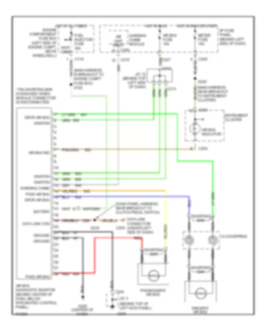
Supplemental Restraint Wiring Diagram for Mercury Tracer GS 1998
List of elements for Supplemental Restraint Wiring Diagram for Mercury Tracer GS 1998:
- (behind top of left kick panel)
- (dash panel harness, near breakout to clutch pedal switch)
- (main harness, in breakout to engine compt fuse box) s102
- * pin shorting bar is engaged when module connector is disconnected
- * red
- A/b unit input
- Air bag diagnostic monitor (behind center of dash, below integrated control panel)
- Air bag fuse 10a
- Air bag ind
- Air bag indicator
- Battery
- C110
- C210
- C213
- C224
- C254
- C255
- C260
- C290
- Clockspring
- Data link con
- Data link connector (under left side of dash)
- Driver's air bag
- Drvr air bag
- Fuel injector fuse 30a
- G200
- G206 (center of dash)
- Ground
- Hot at all times engine compartment fuse box (left side of engine compt, above wheelwell)
- Hot in run
- Hot in run or start
- I/p fuse panel (behind left side of dash)
- Ignition
- Instrument cluster
- J/c 12 (behind top left side of dash)
- J/c 3
- Meter fuse 10a
- Nca
- Pass air bag
- Passenger's air bag
- Red
- S220
- S235
- Shorting bar
- Warning chime
- Warning chime module
 English