SUPPLEMENTAL RESTRAINTS
Supplemental Restraint Wiring Diagram for Mercury Villager GS 1995
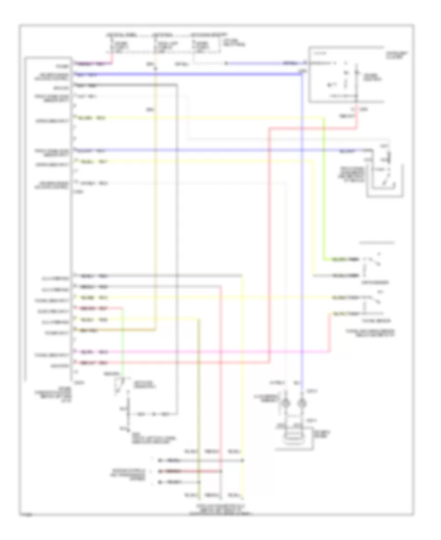
List of elements for Supplemental Restraint Wiring Diagram for Mercury Villager GS 1995:
- "air bag" indicator
- Air bag diagnostic monitor (behind left side of i/p)
- Air bag fuse 14 10a
- C2003
- C2004
- C2013
- C2014
- C268
- Clockspring assembly
- Data link connector (dlc) (behind left side of i/p, on bottom of i/p fuse/relay panel)
- Dlc interface
- Door open input
- Driver's air bag
- Driver's air bag inflation control
- Engine controls and transmissions systems
- Front crash zone sensor (center front of vehicle)
- Front crash zone sensor input
- G200 (top of left cowl panel, near door grommet)
- Ground
- Hot at all times
- Hot in run
- Hot in run or start
- I/p fuse/ relay panel
- Indicator
- Instrument cluster
- Left door jamb switch
- Meter fuse 21 10a
- Nca
- Power
- Power input
- Ps01
- Ps02
- Ps03
- Ps10
- Ps11
- Ps14
- Ps15
- Ps16
- Ps17
- Ps18
- Ps19
- Ps24
- Ps25
- Ps26
- Ps27
- Pse1
- Room lamp fuse 25 15a
- Safing sens input
- Safing sensor
- Tunnel and safing sensor (below center of i/p)
- Tunnel sens input
- Tunnel sensor
 English