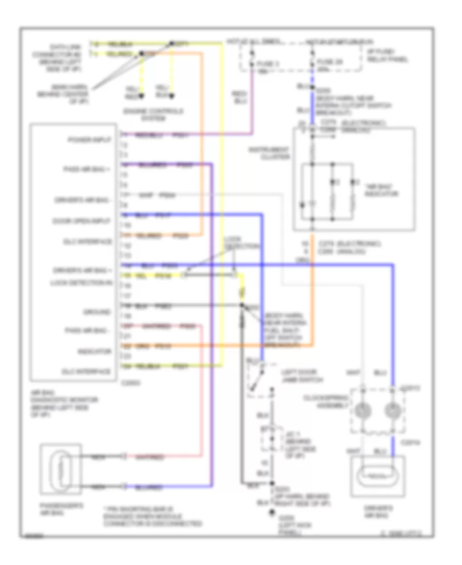
SUPPLEMENTAL RESTRAINTS
Supplemental Restraint Wiring Diagram for Mercury Villager GS 1997
List of elements for Supplemental Restraint Wiring Diagram for Mercury Villager GS 1997:
- "air bag" indicator
- (body harn, near interia fuel shut- off switch breakout)
- (main harn, behind center of i/p)
- * pin shorting bar is engaged when module connector is disconnected
- 14*
- 20*
- Air bag diagnostic monitor (behind left side of i/p)
- C 1995 vftc
- C2003
- C2013
- C2014
- C266
- C268
- C276 (electronic) (analog)
- Clockspring assembly
- Cluster
- Data link connector #2 (behind left side of i/p)
- Dlc interface
- Door open input
- Driver's air bag
- Driver's air bag +
- Driver's air bag -
- Engine controls system
- Fuse 29 10a
- Fuse 3 10a
- G200 (left kick panel)
- Ground
- Hot at all times
- Hot in start or run
- I/p fuse/ relay panel
- Indicator
- Instrument
- J/c 1 (behind left side of i/p)
- Left door jamb switch
- Lock detection
- Lock detection in
- Nca
- Pass air bag +
- Pass air bag -
- Passenger's air bag
- Power input
- Ps01
- Ps03
- Ps04
- Ps05
- Ps06
- Ps15
- Ps17
- Ps18
- Ps20
- Ps21
- Pse2
- S200 (body harn, near interia cutoff switch breakout)
- S202
- S203 (i/p harn, behind right side of i/p)
- S271
 English