
SUPPLEMENTAL RESTRAINTS
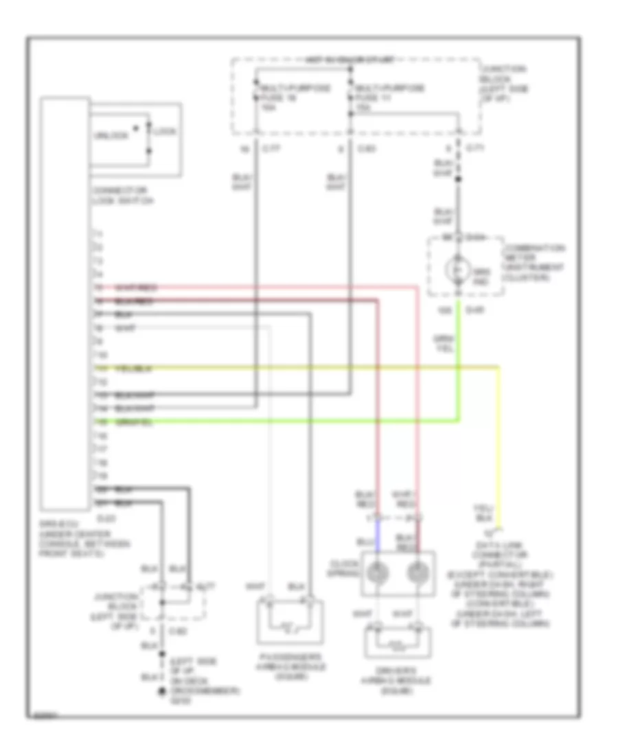
Supplemental Restraint Wiring Diagram for Mitsubishi 3000GT VR-4 1997
List of elements for Supplemental Restraint Wiring Diagram for Mitsubishi 3000GT VR-4 1997:
ANTI-THEFTAIR CONDITIONINGBODY COMPUTERCRUISE CONTROLCOOLING FANCOMPUTER DATA LINESDEFOGGERSANTI-LOCK BRAKESENGINE PERFORMANCEHEADLIGHTSEXTERIOR LIGHTSPOWER ANTENNAGROUND DISTRIBUTIONINTERIOR LIGHTSHORNPASSIVE RESTRAINTSINSTRUMENT CLUSTERPOWER DISTRIBUTIONPOWER MIRRORSPOWER SEATSPOWER TOP/SUNROOFPOWER DOOR LOCKSRADIOTRANSMISSIONPOWER WINDOWSSTARTING/CHARGINGWARNING SYSTEMSSUPPLEMENTAL RESTRAINTSWIPER/WASHER