SUPPLEMENTAL RESTRAINTS
Supplemental Restraint Wiring Diagram for Mitsubishi Eclipse RS 2000
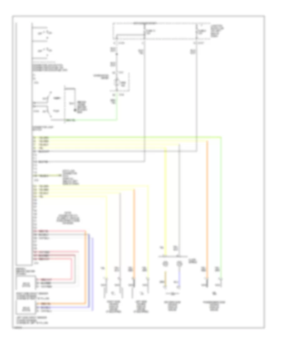
List of elements for Supplemental Restraint Wiring Diagram for Mitsubishi Eclipse RS 2000:
- (behind lower center of dash) g206
- C-104
- C-107
- C-41
- C-42
- C104
- C72
- C74
- Clock spring
- Combination meter
- Connector lock switch
- Connector lock switch (connector coupled: on) (connector uncoupled: off)
- Data link connector (dlc) (partial) (below left side of dash)
- Driver's side air bag module (squib)
- Fuse 13 10a
- Fuse 5 10a
- Hot in on or start
- Junction block (j/b) (on left end of dash)
- Left side air bag module (squib) (if equipped)
- Left side impact sensor (w/side air bags) (in base of left "b" pillar)
- Nca
- Note: connector c74 is used if vehicle is equipped w/side air bags.
- Off
- Passenger's side air bag module (squib)
- Right side air bag module (squib) (if equipped)
- Right side impact sensor (w/side air bags) (in base of right "b" pillar)
- Solid state
- Srs ind.
- Srs-ecu (behind center of dash)
 English