
SUPPLEMENTAL RESTRAINTS
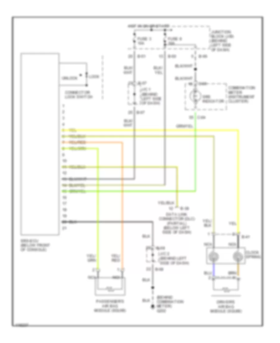
Supplemental Restraint Wiring Diagram for Mitsubishi Eclipse Spyder GS-T 1999
List of elements for Supplemental Restraint Wiring Diagram for Mitsubishi Eclipse Spyder GS-T 1999:
COMPUTER DATA LINESAIR CONDITIONINGDEFOGGERSCRUISE CONTROLANTI-LOCK BRAKESANTI-THEFTCOOLING FANEXTERIOR LIGHTSENGINE PERFORMANCEHEADLIGHTSBODY COMPUTERGROUND DISTRIBUTIONHORNINTERIOR LIGHTSPOWER MIRRORSINSTRUMENT CLUSTERPOWER ANTENNAPOWER DOOR LOCKSPOWER DISTRIBUTIONRADIOPOWER TOP/SUNROOFPOWER WINDOWSSTARTING/CHARGINGSUPPLEMENTAL RESTRAINTSTRANSMISSIONPOWER SEATSWARNING SYSTEMSWIPER/WASHER