SUPPLEMENTAL RESTRAINTS
Supplemental Restraints Wiring Diagram (1 of 2) for Mitsubishi Galant ES 2003

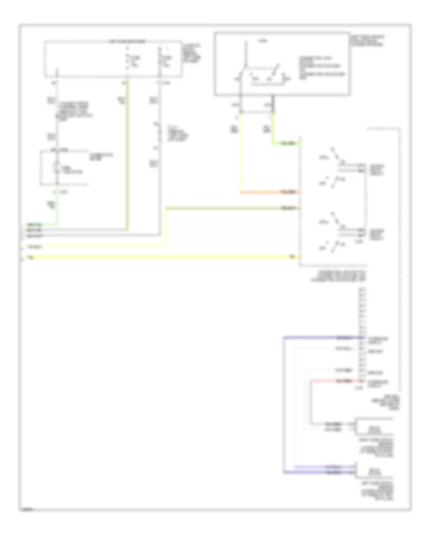
List of elements for Supplemental Restraints Wiring Diagram (1 of 2) for Mitsubishi Galant ES 2003:
- (behind left side of dash) g5
- (in dash wiring harness, at breakout for hazard warning light switch) s054
- (under dash, to right of center reinforce- ment) g11
- Air bag drive circuit
- C-44
- Clock spring
- Connector lock switch (connector coupled: on) (connector uncoupled: off)
- Connector lock switch (connector coupled: on) connector uncoupled: off)
- Data
- Data link connector (dlc) (partial) (under left side of dash)
- Detection circuit
- Driver's side air bag module squib
- Gnd
- J/c 1 (behind left side of dash)
- Nca
- Off
- Passenger's side air bag module squib
- Power
- Right side air bag module squib (w/side air bag module)
- Srs ecu (behind lower center of dash)
- Warning light drive circuit
Supplemental Restraints Wiring Diagram (2 of 2) for Mitsubishi Galant ES 2003
List of elements for Supplemental Restraints Wiring Diagram (2 of 2) for Mitsubishi Galant ES 2003:
- (in dash wiring harness, near breakout for foglight switch) s097
- Air bag drive circuit
- C-29
- C-30
- C-45
- C-84
- Combination meter
- Connector lock switch (connector coupled: on) (connector uncoupled: off)
- Fuse 7.5a
- Ground
- Hot in on or start
- Interface circuit
- J/c 1 (behind left side of dash)
- Junction block (behind left side of dash)
- Left side air bag module squib (w/side air bags)
- Left side impact sensor (w/side air bags) (at base of left "b" pillar)
- Nca
- Off
- Right side impact sensor (w/side air bags) (at base of right "b" pillar)
- Solid state
- Srs ecu (behind lower center of dash)
- Srs indicator