SUPPLEMENTAL RESTRAINTS
Supplemental Restraint Wiring Diagram for Mitsubishi Montero Limited 2001
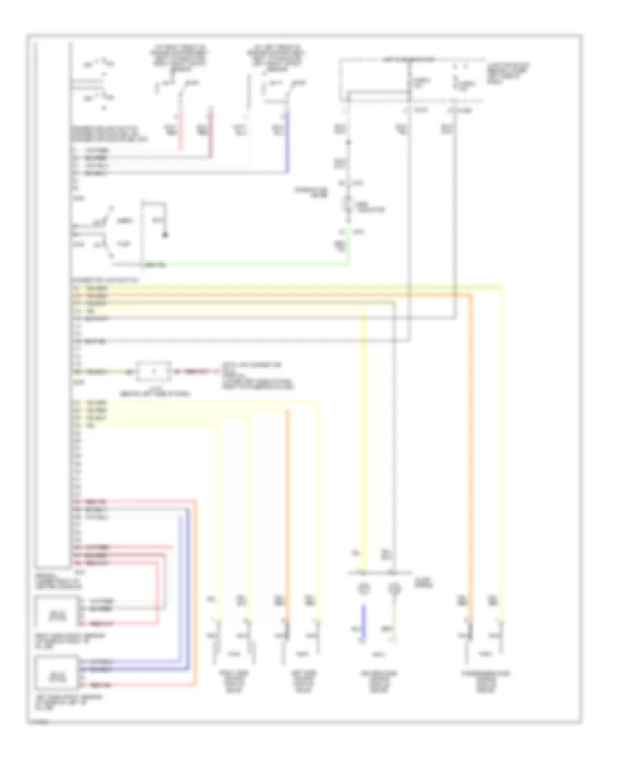
List of elements for Supplemental Restraint Wiring Diagram for Mitsubishi Montero Limited 2001:
- (at left front of engine compartment, next to radiator) left front impact sensor
- (at right front of engine compartment, next to radiator) right front impact sensor
- Clock spring
- Combination meter
- Connector lock switch
- Connector lock switch (connector coupled: on) (connector uncoupled: off)
- D-03
- D-04
- D-209
- D-210
- Data link connector (dlc) (partial) (lower left side of dash, right of steering column)
- Driver's side air bag module (squib)
- E-07
- E-08
- Fuse 6 10a
- Fuse 8 10a
- Hot in on or start
- J/c 5 (behind left side of dash)
- Junction block (behind lower left side of dash)
- Left side air bag module squib
- Left side impact sensor (at base of left "b" pillar)
- Nca
- Off
- Passenger's side air bag module (squib)
- Right side air bag module squib
- Right side impact sensor (at base of right "b" pillar)
- Solid state
- Srs indicator
- Srs-ecu (under front of center console)
 English