
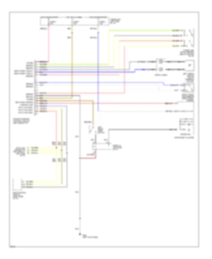
SUPPLEMENTAL RESTRAINTS
Supplemental Restraint Wiring Diagram for Nissan Quest GXE 1994
List of elements for Supplemental Restraint Wiring Diagram for Nissan Quest GXE 1994:
COOLING FANBODY COMPUTERANTI-LOCK BRAKESAIR CONDITIONINGCOMPUTER DATA LINESCRUISE CONTROLENGINE PERFORMANCEDEFOGGERSHORNEXTERIOR LIGHTSHEADLIGHTSINTERIOR LIGHTSGROUND DISTRIBUTIONINSTRUMENT CLUSTERPOWER ANTENNAPASSIVE RESTRAINTSPOWER DISTRIBUTIONSHIFT INTERLOCKSPOWER DOOR LOCKSTRANSMISSIONPOWER SEATSPOWER MIRRORSSUPPLEMENTAL RESTRAINTSPOWER WINDOWSPOWER TOP/SUNROOFSTARTING/CHARGINGRADIOWARNING SYSTEMSWIPER/WASHER