SUPPLEMENTAL RESTRAINTS
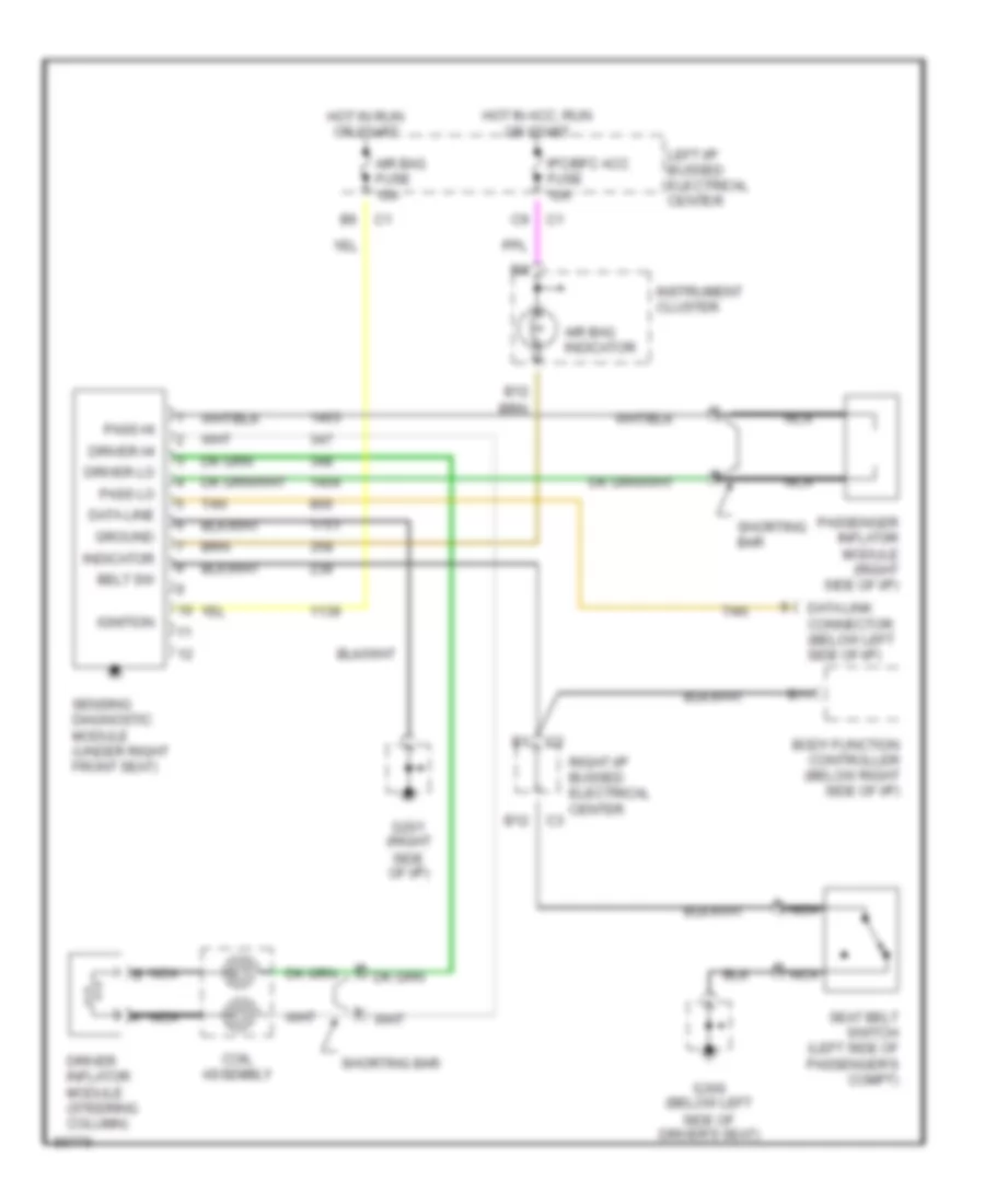
Supplemental Restraint Wiring Diagram for Oldsmobile Cutlass 1997
List of elements for Supplemental Restraint Wiring Diagram for Oldsmobile Cutlass 1997:
- Air bag fuse 10a
- Air bag indicator
- B11
- B12
- Belt sw
- Body function controller (below right side of i/p)
- Coil assembly
- Data line
- Data link connector (below left side of i/p)
- Driver hi
- Driver inflator module (steering column)
- Driver lo
- G201 (right side of i/p)
- G300 (below left side of driver's seat)
- Ground
- Hot in acc, run or start
- Hot in run or start
- Ignition
- Indicator
- Instrument cluster
- Ipc/bfc acc fuse 10a
- Left i/p bussed electrical center
- Nca
- Nca b
- Pass hi
- Pass lo
- Passenger inflat0r module (right side of i/p)
- Right i/p bussed electrical center
- Seat belt switch (left side of passenger's compt)
- Sensing diagnostic module (under right front seat)
- Shorting bar
- Tan
 English