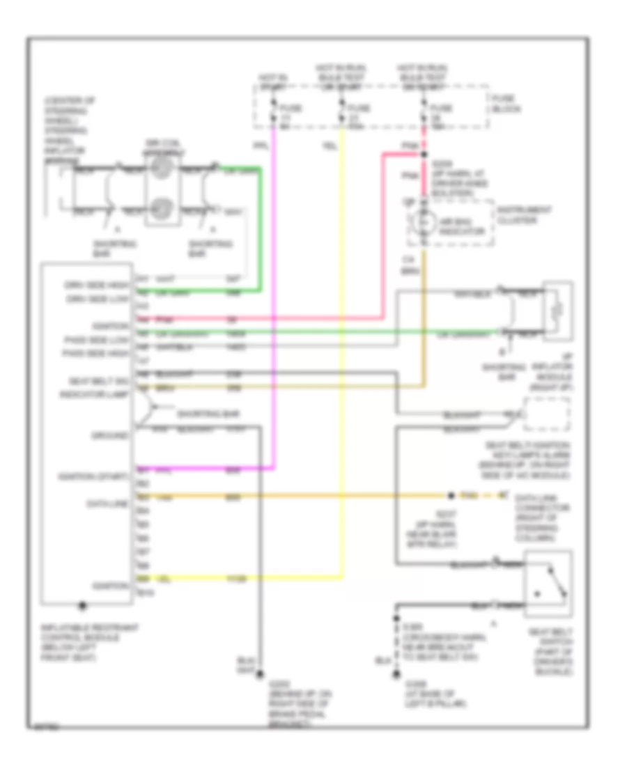
SUPPLEMENTAL RESTRAINTS
Supplemental Restraint Wiring Diagram for Oldsmobile Cutlass Supreme SL 1997
List of elements for Supplemental Restraint Wiring Diagram for Oldsmobile Cutlass Supreme SL 1997:
- (center of steering wheel) steering wheel inflator module
- A10
- Air bag indicator
- B nca
- B10
- Bar
- Data line
- Data link connector (right of steering column)
- Driv side high
- Driv side low
- Fuse 10a
- Fuse 15a
- Fuse 5a
- Fuse block
- G202 (behind i/p, on right side of brake pedal bracket)
- G308 (at base of left b pillar)
- Ground
- Hot in run, bulb test or start
- Hot in start
- I/p inflator module (right i/p)
- Ignition
- Ignition (start)
- Indicator lamp
- Inflatable restraint control module (below left front seat)
- Instrument cluster
- Nca
- Pass side high
- Pass side low
- Pnk
- S209 (i/p harn, at driver knee bolster)
- S237 (i/p harn, near blwr mtr relay)
- S305 (crossbody harn, near breakout to seat belt sw)
- Seat belt sig
- Seat belt switch (part of driver's buckle)
- Seat belt/ ignition key/ lamps alarm (behind i/p, on right side of a/c module)
- Shorting
- Shorting bar
- Sir coil assembly
- Tan
 English