SUPPLEMENTAL RESTRAINTS
Supplemental Restraint Wiring Diagram for Oldsmobile Intrigue GL 2000
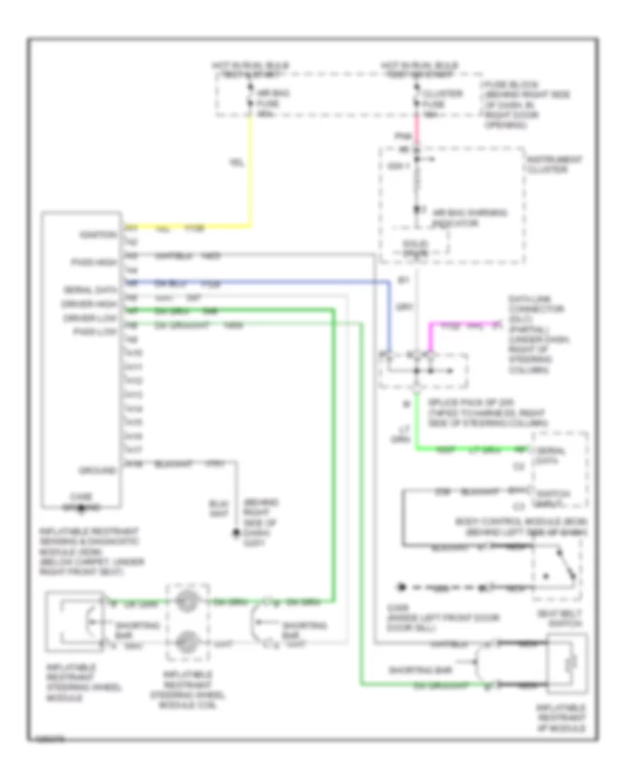
List of elements for Supplemental Restraint Wiring Diagram for Oldsmobile Intrigue GL 2000:
- (behind right side of dash) g201
- A10
- A11
- A12
- A13
- A14
- A15
- A16
- A17
- A18
- Air bag fuse 15a
- Air bag warning indicator
- B11
- Body control module (bcm) (behind left side of dash)
- Case ground
- Cluster fuse 10a
- Data link connector (dlc) (partial) (under dash, right of steering column)
- Driver high
- Driver low
- Fuse block (behind right side of dash, in right door opening)
- G309 (inside left front door door sill)
- Ground
- Hot in run, bulb test & start
- Hot in run, bulb test or start
- Ign 1
- Ignition
- Inflatable restraint i/p module
- Inflatable restraint sensing & diagnostic module (sdm) (below carpet, under right front seat)
- Inflatable restraint steering wheel module
- Inflatable restraint steering wheel module coil
- Instrument cluster
- Nca
- Pass high
- Pass low
- Pnk
- Seat belt switch
- Serial data
- Shorting bar
- Solid state
- Splice pack sp 205 (taped to harness, right side of steering column)
- Switch input
 English