SUPPLEMENTAL RESTRAINTS
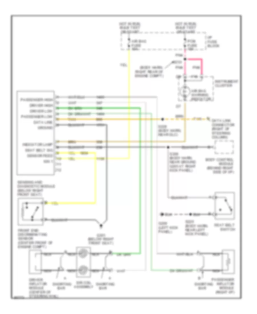
Supplemental Restraint Wiring Diagram for Pontiac Bonneville SE 1997
List of elements for Supplemental Restraint Wiring Diagram for Pontiac Bonneville SE 1997:
- (body harn, right rear of engine compt)
- Air bag fuse 10a
- Air bag warning indicator
- B nca
- Bar
- Body control module (behind right side of i/p)
- Data line
- Data link connector (right of steering column)
- Driver high
- Driver inflator module (center of steering whl)
- Driver low
- F16
- Front end discriminating sensor (center front of engine compt)
- G200 (left kick panel)
- G301 (below right front seat)
- Ground
- Hot in run, bulb test or start
- I/p fuse block
- Ign 1
- Indicator lamp
- Instrument cluster
- Nca
- Passenger high
- Passenger inflator module (right i/p)
- Passenger low
- Pcm fuse 10a
- Pnk
- S225 (body harn, near left kick panel)
- S226 (body harn, near dlc)
- S233
- S309 (body harn, near ground g203 at right kick panel)
- Seat belt sig
- Seat belt switch
- Sensing and diagnostic module (below right front seat)
- Sensor feed
- Shorting
- Sir coil assembly
- Tan
 English