SUPPLEMENTAL RESTRAINTS
Supplemental Restraints Wiring Diagram (1 of 2) for Pontiac G5 GT 2008

List of elements for Supplemental Restraints Wiring Diagram (1 of 2) for Pontiac G5 GT 2008:
- (on lower corner of passenger's door)
- (under center console, near sensing & diagnostic module (sdm)) g306
- Air bag fuse 13 10a
- Batt positive voltage
- Body control module (bcm) (under center dash, on right side of center console)
- Case ground
- Driver seat belt pretensioner (left "b" pillar)
- Gmlan serial data
- Ground
- High control
- Hot at all times
- Hot in run or start
- Hvac/ ip ign fuse 16 10a
- Ignition 1 voltage
- Ind
- Inflatable restraint instrument panel (ip) module (right side of dash, above glove compartment)
- Inflatable restraint sensing & diagnostic module (sdm) (under center console, behind parking brake)
- Inflatable restraint steering wheel module
- Inflatable restraint steering wheel module coil (on steering column, behind steering wheel)
- Left inflatable restraint side impact sensor (sis) (on lower corner of driver's door)
- Left seat belt sw sig
- Logic
- Low control
- Low ref
- Low reference
- Occupant sens sig
- Passenger seat belt pretensioner (right "b" pillar)
- Pin shorting bars engaged
- Pnk
- Right inflatable restraint side impact sensor (sis)
- Right seat belt sw sig
- Sdm fuse 10a
- Sensor signal
- Sensor voltage
- Shorting bar
- Stage 1
- Stage 2
- Tan
- Underhood fuse block (in engine compt, next to left strut tower)
- W/ left & right roof side inflatable system
- When module connector is disconnected from harness: (shorting bars are connected between following pins: 8-9 & 10-11)
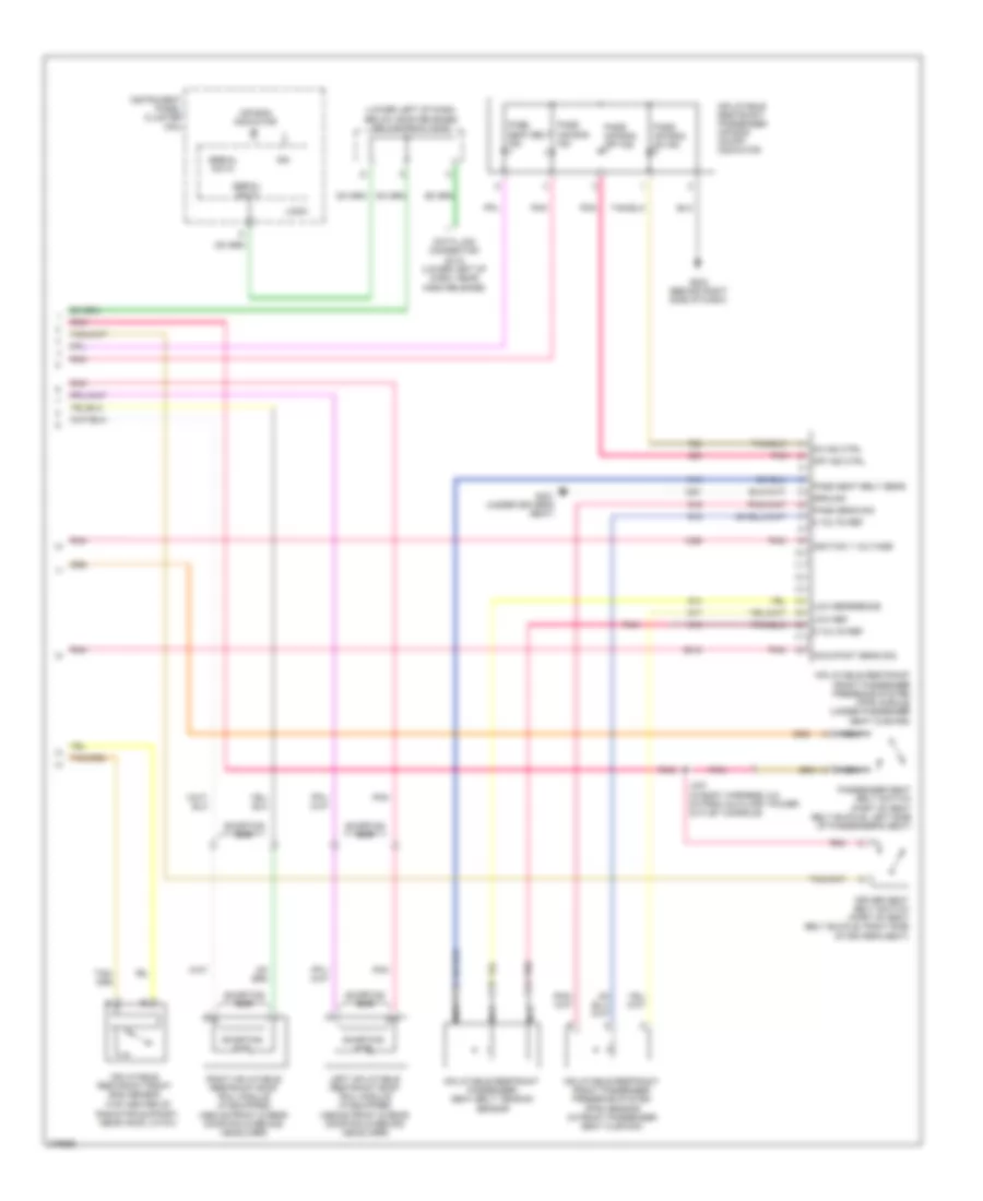
Supplemental Restraints Wiring Diagram (2 of 2) for Pontiac G5 GT 2008
List of elements for Supplemental Restraints Wiring Diagram (2 of 2) for Pontiac G5 GT 2008:
- (lower left of dash, below hood release) splice pack jx200
- (top center of radiator support, near hood latch)
- 5 volts ref
- Air bag indicator
- Data link connector (dlc) (lower left of dash, near hood release)
- Driver seat belt switch (part of seat belt buckle, right side of driver's seat)
- G203 (behind right side of dash)
- G301 (under driver's seat)
- Ground
- Ign
- Ignition 1 voltage
- Inflatable restraint front end sensor
- Inflatable restraint front passenger presence system (pps) module (under passenger seat cushion)
- Inflatable restraint front passenger presence system (pps) sensor (in front passenger seat cushion)
- Inflatable restraint passenger air bag on/off indicator
- Inflatable restraint passenger seat belt tension sensor
- Instrument panel cluster (ipc)
- J337 (in body harness, 6.5 cm from auxiliary power outlet console)
- Left inflatable restraint roof rail module (if equipped) (above front & rear door rails behind headliner)
- Logic
- Low ref
- Low reference
- Nca
- Occupant sens sig
- Off ind ctrl
- On ind ctrl
- Pass air bag ind
- Pass air bag off ind
- Pass air bag on ind
- Pass seat belt ind
- Pass seat belt sens
- Pass sens sig
- Passenger seat belt switch (part of seat belt buckle, left side of passenger's seat)
- Pnk
- Pnk a
- Right inflatable restraint roof rail module (if equipped) (above front & rear door rails behind headliner)
- Serial data
- Shorting bar