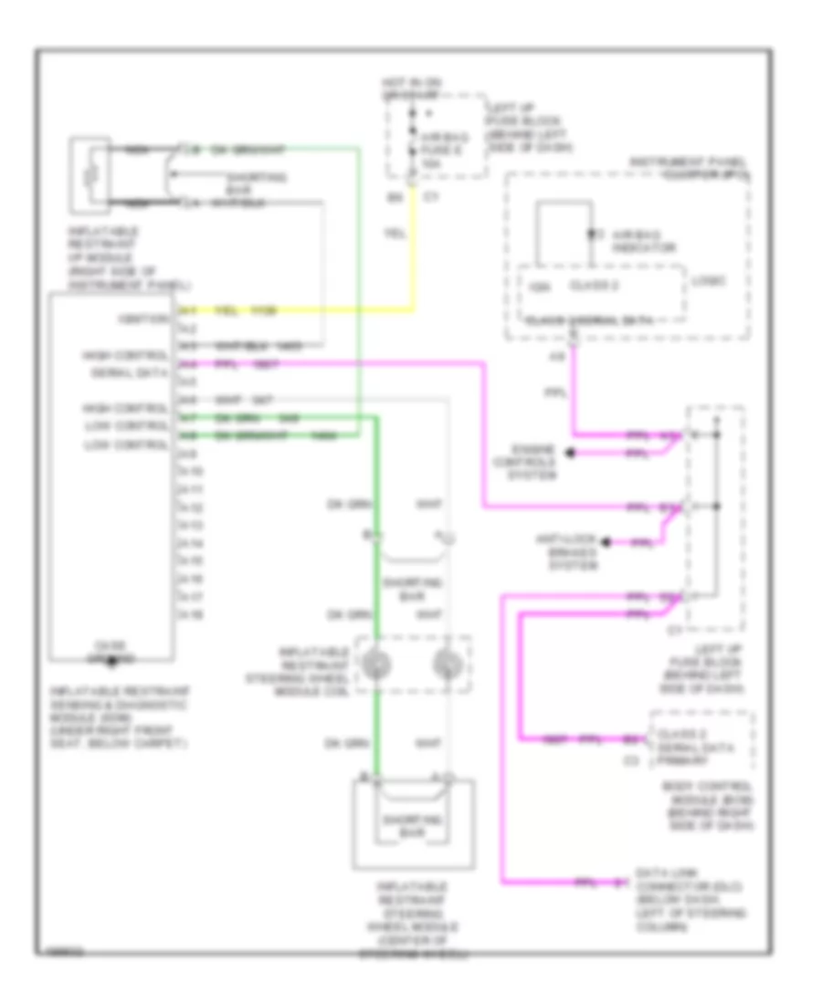
SUPPLEMENTAL RESTRAINTS
Supplemental Restraints Wiring Diagram for Pontiac Grand Am GT 2005
List of elements for Supplemental Restraints Wiring Diagram for Pontiac Grand Am GT 2005:
- A10
- A11
- A12
- A13
- A14
- A15
- A16
- A17
- A18
- Air bag fuse e 10a
- Air bag indicator
- Anti-lock brakes system
- Body control module (bcm) (behind right side of dash)
- Case ground
- Class 2
- Class 2 serial data
- Class 2 serial data primary
- Data link connector (dlc) (below dash, left of steering column)
- Engine controls system
- High control
- Hot in on or start
- Ign
- Ignition
- Inflatable restraint i/p module (right side of instrument panel)
- Inflatable restraint sensing & diagnostic module (sdm) (under right front seat, below carpet)
- Inflatable restraint steering wheel module (center of steering wheel)
- Inflatable restraint steering wheel module coil
- Instrument panel cluster (ipc)
- Left i/p fuse block (behind left side of dash)
- Logic
- Low control
- Nca
- Serial data
- Shorting bar
 Русский