SUPPLEMENTAL RESTRAINTS
Supplemental Restraints Wiring Diagram (1 of 2) for Pontiac Vibe 2003

List of elements for Supplemental Restraints Wiring Diagram (1 of 2) for Pontiac Vibe 2003:
- Acc
- Air bag ind ctrl
- C10
- C11
- C12
- Computer data lines system
- Control
- Diagn request
- Driver seat high
- Driver seat low
- Driver seat position sensor (right seat rail of driver seat)
- G201
- Ground
- High control
- Hot at all times
- Ignition switch
- Inflatable restraint i/p module (right top of instrument panel)
- Inflatable restraint left front discri- minating sensor (at left front of eng compt, mounted to frame rail)
- Inflatable restraint right front discri- minating sensor (at right front of eng compt, behind right headlight)
- Inflatable restraint sensing & diagnostic module (at front center console, below shifter assembly)
- Inflatable restraint steering wheel module (in steering wheel)
- Inflatable restraint steering wheel module coil
- Ing voltage (+)
- Instrument panel fuse block (left of steering column, behind storage compt)
- Lock
- Low control
- Lsp +
- Lsp -
- Nca
- Power
- Power distribution system
- Powertrain control module (behind right side of dash)
- Sens input high
- Sens input low
- Serial data line
- Shorting bar
- Signal
- Sp 201 (behind right body hinge pillar trim panel)
- Start
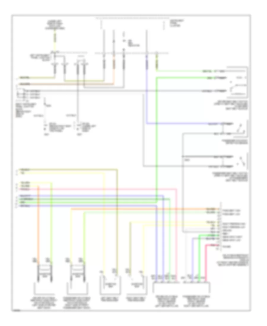
Supplemental Restraints Wiring Diagram (2 of 2) for Pontiac Vibe 2003
List of elements for Supplemental Restraints Wiring Diagram (2 of 2) for Pontiac Vibe 2003:
- (under left side of dash) data link connector obd2
- Air bag indicator
- Driver inflatable restraint side impact inflator module (left side of driver seat back)
- Driver inflatable restraint side impact sensor (at bottom of left center pillar)
- Driver seat belt switch (open w/ seat belt buckled) (in driver's seat belt buckle)
- G201
- Ground
- Inflatable restraint sensing & diagnostic module (at front center console, below shifter assembly)
- Instrument panel cluster
- Left instrument panel junction block
- Left seat belt pretensioner
- Nca
- Pass seat high
- Pass seat low
- Passenger inflatable restraint side impact inflator module (right side of front passenger seat back)
- Passenger inflatable restraint side impact sensor (at bottom of right center pillar)
- Passenger occupant detection sensor
- Passenger seat belt switch (open w/ seat belt buckled) (in passenger's seat belt buckle)
- Pnk
- Power
- Rbe +
- Right instrument panel junction block (behind right side of dash)
- Right pretens high
- Right pretens low
- Right seat belt pretensioner
- S222
- S223
- Sens input hight
- Sens input low
- Shorting bar
- Sp 200 (under left side of dash)
- Sp 201 (behind right body hinge pillar trim panel)