SUPPLEMENTAL RESTRAINTS
Supplemental Restraints Wiring Diagram (1 of 2) for Toyota Corolla LE 2003

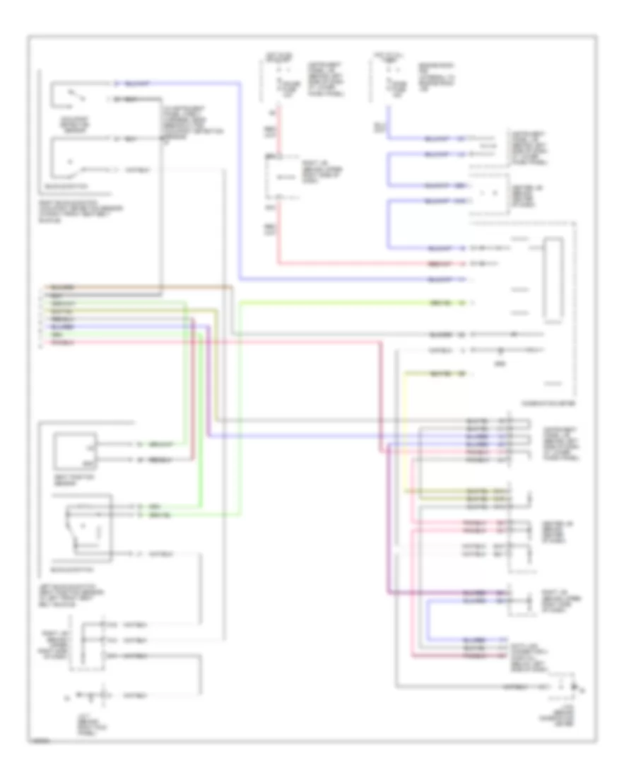
List of elements for Supplemental Restraints Wiring Diagram (1 of 2) for Toyota Corolla LE 2003:
- (front passenger air bag assembly) air bag squib
- (on left side door sill plate area) (if equipped) left side air bag sensor
- (steering wheel pad) air bag squib
- +sl
- +sr
- -sl
- -sr
- A12
- A13
- A14
- Acc
- Air bag sensor assembly (below front of center console)
- Am2
- D2+
- D2-
- Engine control module (behind right side of dash, below glove box)
- Esl
- Esr
- F/ps
- Fr-
- Fsl
- Fsr
- Gsw2
- H10
- Hot at all times
- I10
- Ig2
- Ignition switch
- Instrument panel j/b (behind left side of dash, at lower finish panel)
- J/c 6 (behind left side of dash)
- J/c 7 (behind right kick panel)
- Lbe+
- Left front air bag sensor (behind left side of grille)
- Left pretensioner (at bottom of left "b" pillar)
- Left side air bag squib (if equipped)
- Lock
- Lsp+
- Lsp-
- P2+
- P2-
- Pl+
- Pl-
- Pnk
- Pr+
- Rbe+
- Right front air bag sensor (behind right side of grille)
- Right pretensioner (at bottom of right "b" pillar)
- Right side air bag sensor (if equipped) (on right side door sill plate area)
- Right side air bag squib (if equipped)
- Sfl+
- Sfl-
- Sfr+
- Sfr-
- Sil
- Ssl-
- Ssr-
- Start
- Vupl
- Vupr
Supplemental Restraints Wiring Diagram (2 of 2) for Toyota Corolla LE 2003
List of elements for Supplemental Restraints Wiring Diagram (2 of 2) for Toyota Corolla LE 2003:
- (in instrument panel wire 3 harness, near breakout for occupant detection sensor) i6
- A11
- A14
- A15
- B16
- B18
- B21
- B22
- Buckle switch
- C13
- C14
- C15
- C19
- C20
- Center j/b (behind center of dash)
- Combination meter
- Data link connector 3 (partial) (below left side of dash)
- Dome fuse 15a
- Engine room r/b (intergal to engine room j/b)
- Gauge fuse 10a
- Gnd
- Hot at all times
- Hot in on or start
- Instrument panel j/b (behind left side of dash at lower finish panel)
- Instrument panel j/b (behind left side of dash, at lower finish panel)
- J/c 6 (behind combination meter)
- J/c 7 (behind right kick panel)
- Left buckle switch (seat position sensor) (in left front seat belt buckle)
- Occupant detection sensor
- Right buckle switch (occupant detection sensor) (in right front seat belt buckle)
- Right j/b (behind upper right side of dash)
- Seat position sensor
- Srs