SUPPLEMENTAL RESTRAINTS
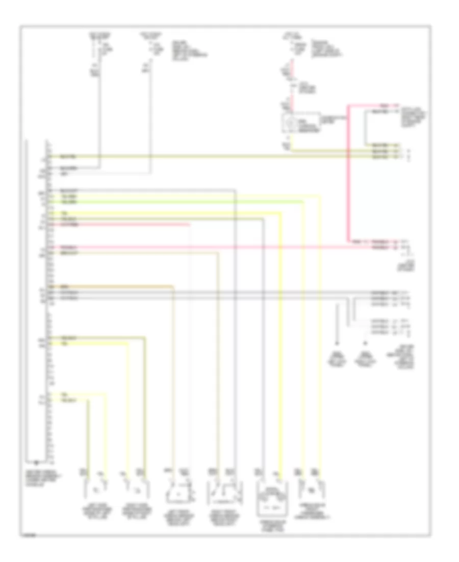
Supplemental Restraint Wiring Diagram for Toyota Sienna CE 1998
List of elements for Supplemental Restraint Wiring Diagram for Toyota Sienna CE 1998:
- Acc
- Airbag squib (front passenger airbag assembly)
- Airbag squib (steering wheel pad)
- Center airbag sensor assembly (under center console)
- Cig fuse 15a
- Combination meter
- Data link connector 1 (right rear of engine compt)
- Driver side j/b 1 (behind dash, left of steering column)
- Engine room j/b 2 (left side of engine compt)
- G200 (upper left kick panel)
- G203 (upper right kick panel)
- Hot at all times
- Hot in run or acc
- Hot in run or start
- Ig2
- Ign fuse 5a
- J/c 6 (center of dash)
- J/c 8 (center of dash)
- Left front airbag sensor (behind left headlight)
- Left side pretensioner (base of left "b" pillar)
- Pl+
- Pl-
- Pnk
- Pr+
- Pr-
- Right front airbag sensor (behind right headlight)
- Right side pretensioner (base of right "b" pillar)
- Sl+
- Sl-
- Spiral cable
- Sr+
- Sr-
- Srs warning indicator
- Srs-b fuse 10a
 English