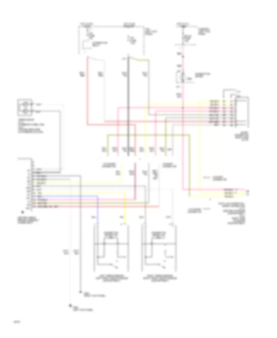
SUPPLEMENTAL RESTRAINTS
Supplemental Restraint Wiring Diagram for Toyota T100 SR5 1994
List of elements for Supplemental Restraint Wiring Diagram for Toyota T100 SR5 1994:
- +sl
- +sr
- -sl
- -sr
- 2.7l
- 3.0l
- Acc
- Airbag squib (2.7l) (steering wheel pad) (3.0l) (for driver's side) (in steering column)
- C17
- Center airbag sensor assembly (under seat)
- Cig fuse 15a
- Combination meter
- Connection detection pin
- D11
- Data link conector 1 (check connector) (2.7l) (center of engine compartment) (3.0l) (right side of engine compartment)
- Ecu-b fuse 15a
- Fuse box (left kick panel
- G200 (left kick panel)
- G203 (right kick panel)
- Hot at all times
- Hot in acc or on
- Hot in on or start
- Ig2
- Ign fuse 7.5a
- Integration relay
- J/b 1 (left kick panel)
- Left airbag sensor (left front side of engine compartment)
- Red
- Right airbag sensor (right front side of engine compartment)
- Short connector (right side of i/p)
- Srs
- W/o short connector
- W/short connector
 English