SUPPLEMENTAL RESTRAINTS
Supplemental Restraint Wiring Diagram for Toyota Tundra SR5 2000
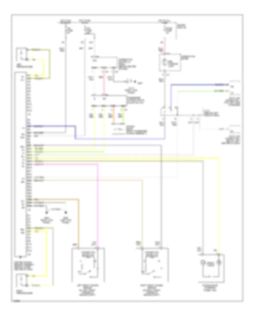
List of elements for Supplemental Restraint Wiring Diagram for Toyota Tundra SR5 2000:
- A10
- A11
- A12
- Acc
- Acc fuse 15a
- Air bag squib (front passenger air bag assembly)
- Air bag squib (steering wheel pad)
- B10
- B11
- B12
- B13
- B14
- B15
- B16
- B17
- B18
- B19
- B20
- B21
- B22
- B23
- B24
- B25
- B26
- B27
- B28
- C10
- C11
- C12
- Center air bag sensor assembly (behind lower center of dash)
- Combination meter
- Connection detection pin
- Data link connector 1 (top left side of engine)
- Data link connector 3 (below left center of dash)
- Driver side j/b
- Ecu+
- Ecu-
- Ecu-b fuse 5a
- G10
- G200 (left kick panel)
- G203
- G203 (right kick panel)
- Gnd
- Gnd1
- Hot at all times
- Hot in acc or on
- Hot in on or start
- I24
- I25
- Ig2
- Ign fuse 5a
- Ind
- Integration control & panel (behind center of dash)
- J/c 13 (right kick panel)
- J/c 5 (behind left side of dash)
- Left front air bag sensor (on left front corner of engine compt)
- Left pretensioner
- Passenger air bag manual on-off switch
- Pind
- Pl+
- Pl-
- Red
- Right front air bag sensor (on right front corner of engine compt)
- Right pretensioner
- Rr+
- Rr-
- Sil
- Sl-
- Spiral cable
- Sqb+
- Sqb-
- Sr+
- Sr-
- Srs warning light
 Русский