
SUPPLEMENTAL RESTRAINTS
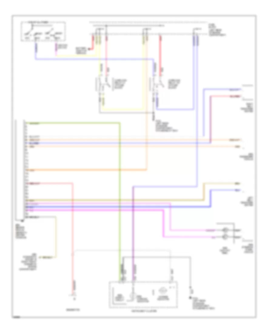
Supplemental Restraint Wiring Diagram for Volvo 850 GLT 1995
List of elements for Supplemental Restraint Wiring Diagram for Volvo 850 GLT 1995:
AIR CONDITIONINGANTI-LOCK BRAKESANTI-THEFTENGINE PERFORMANCEEXTERIOR LIGHTSGROUND DISTRIBUTIONHEADLIGHTSHORNINSTRUMENT CLUSTERINTERIOR LIGHTSMEMORY SYSTEMSPOWER ANTENNAPOWER DISTRIBUTIONPOWER DOOR LOCKSPOWER MIRRORSPOWER SEATSPOWER TOP/SUNROOFPOWER WINDOWSRADIOSHIFT INTERLOCKSSTARTING/CHARGINGSUPPLEMENTAL RESTRAINTSTRANSMISSIONWARNING SYSTEMSWIPER/WASHERCOMPUTER DATA LINESCOOLING FANDEFOGGERSCRUISE CONTROL