
SUPPLEMENTAL RESTRAINTS
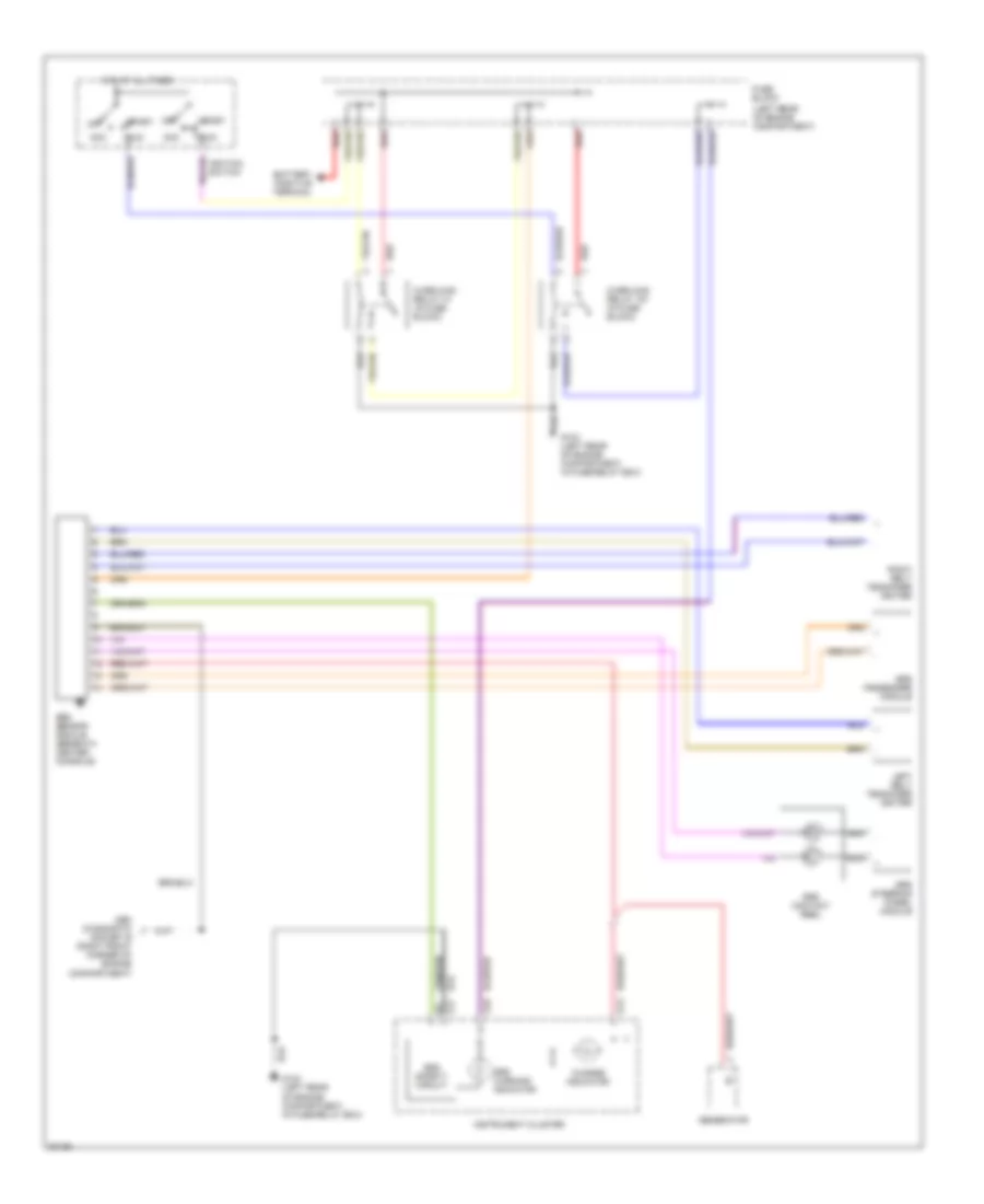
Supplemental Restraint Wiring Diagram for Volvo 850 T-5 1997
List of elements for Supplemental Restraint Wiring Diagram for Volvo 850 T-5 1997:
ANTI-THEFTANTI-LOCK BRAKESAIR CONDITIONINGCOMPUTER DATA LINESCOOLING FANGROUND DISTRIBUTIONEXTERIOR LIGHTSCRUISE CONTROLHEADLIGHTSINTERIOR LIGHTSENGINE PERFORMANCEHORNINSTRUMENT CLUSTERMEMORY SYSTEMSPOWER ANTENNAPOWER WINDOWSPOWER SEATSSHIFT INTERLOCKSRADIOPOWER DISTRIBUTIONPOWER MIRRORSPOWER DOOR LOCKSPOWER TOP/SUNROOFSUPPLEMENTAL RESTRAINTSSTARTING/CHARGINGTRANSMISSIONDEFOGGERSWARNING SYSTEMSWIPER/WASHER