SUPPLEMENTAL RESTRAINTS
Supplemental Restraints Wiring Diagram (1 of 3) for Volvo C30 T-5 2012

List of elements for Supplemental Restraints Wiring Diagram (1 of 3) for Volvo C30 T-5 2012:
- (under driver's seat) driver's seat position sensor
- (under front passenger's seat) passenger's seat position sensor
- 64/111
- 64/30
- 64/31
- 64/425
- Ceiling light switch unit
- Cem
- Central electronic module (cem) (behind right side of dash)
- Comfort functions relay
- Contact reel (top of steering column)
- Driver side air bag igniter (in steering wheel)
- Driver side air bag igniter stage 2 (in steering wheel)
- Engine compartment distribution box (left side of engine compt)
- Fuse f3 60a
- Fuse f44 10a
- Fuse f49 10a
- G10 (base of right "a" pillar)
- G84 (base of right "a" pillar)
- Gnd
- Hot at all times
- Hot in start or run
- Left front impact sensor (behind left side of front bumper)
- Nca
- Passenger side air bag igniter (behind right side of dash)
- Passenger side air bag igniter stage 2 (behind right side of dash)
- Passenger side air bag switch
- Right front impact sensor (behind right side of front bumper)
- Steering column igniter (top of steering column)
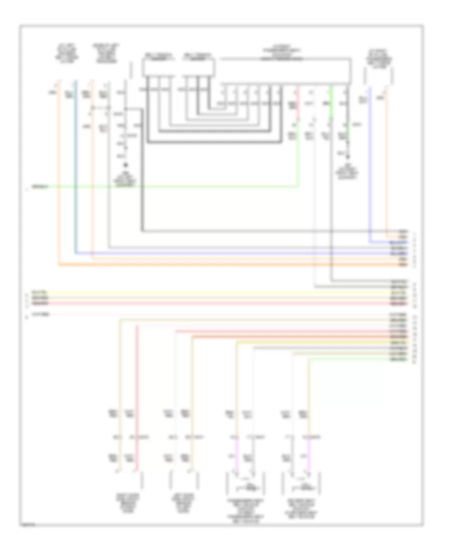
Supplemental Restraints Wiring Diagram (2 of 3) for Volvo C30 T-5 2012
List of elements for Supplemental Restraints Wiring Diagram (2 of 3) for Volvo C30 T-5 2012:
- (at left "b" pillar) driver's belt force limiter
- (at right "b" pillar)
- (base of left "b" pillar) driver's lap belt tensioner
- (in front passenger's seat) occupant weight sensor (ows)
- 64/30
- 64/31
- 64/41
- 64/43
- Belt tension sensor
- Driver's seat belt buckle contact (in driver's seat belt buckle)
- G66 (on left front seat support)
- G67 (on right front seat support)
- Hall effect
- Left door side impact sensor (in left door)
- Nca
- Passenger's belt force limiter
- Passenger's seat belt buckle contact (in front passenger's seat belt buckle)
- Right door side impact sensor (in right door)
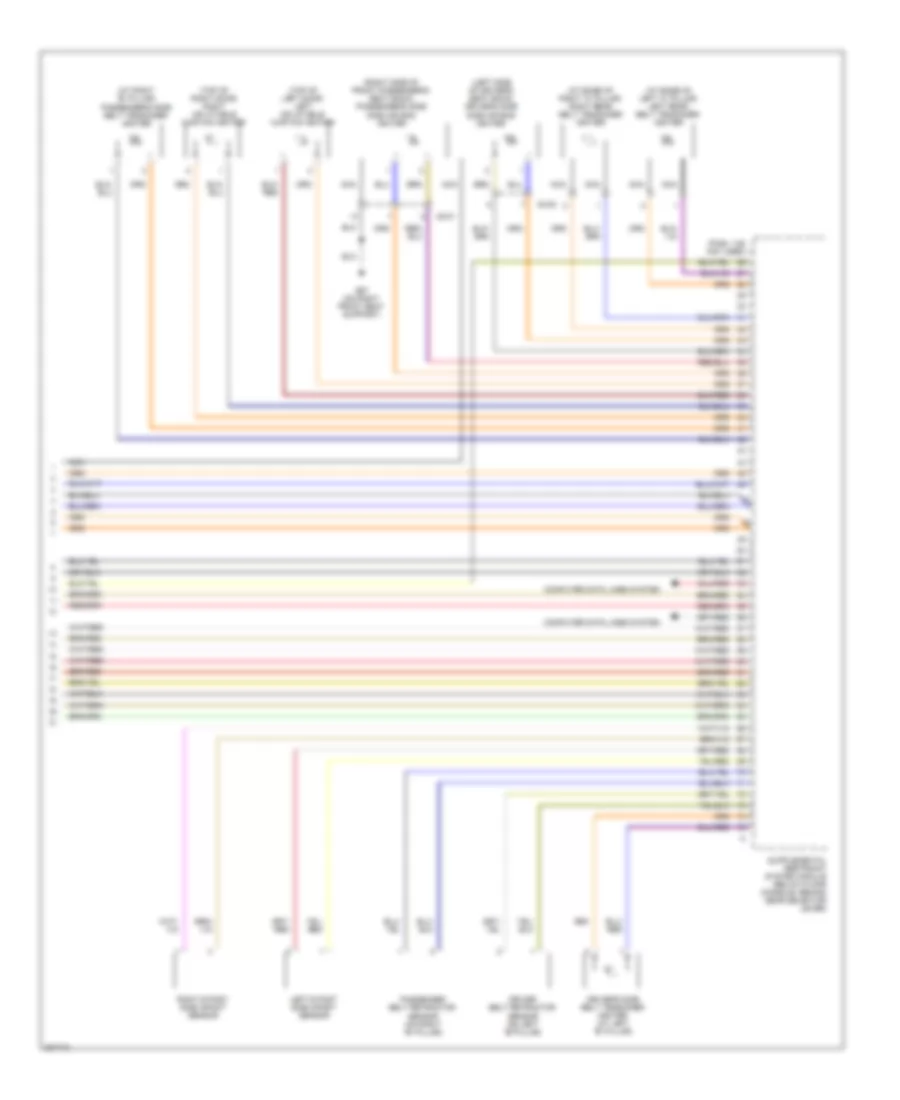
Supplemental Restraints Wiring Diagram (3 of 3) for Volvo C30 T-5 2012
List of elements for Supplemental Restraints Wiring Diagram (3 of 3) for Volvo C30 T-5 2012:
- (at base of left "c" pillar) left rear belt tensioner igniter
- (at base of right "c" pillar) right rear belt tensioner igniter
- (at right "b" pillar) passenger's side belt tensioner igniter
- (left side of driver's seat back) driver's side side air bag igniter
- (pins: 1-25 not used)
- (right side of front passenger's seat back) passenger's side side air bag igniter
- (top of left door) left inflatable curtain igniter
- (top of right door) right inflatable curtain igniter
- 64/30
- 64/31
- Computer data lines system
- Driver belt retractor sensor (on left "b" pillar)
- Driver's side belt tensioner igniter (at left "b" pillar)
- G67 (on right front seat support)
- Left b post side impact sensor
- Nca
- Passenger belt retractor sensor (on right "b" pillar)
- Right b post side impact sensor