СИСТЕМА КРУИЗКОНТРОЛЯ
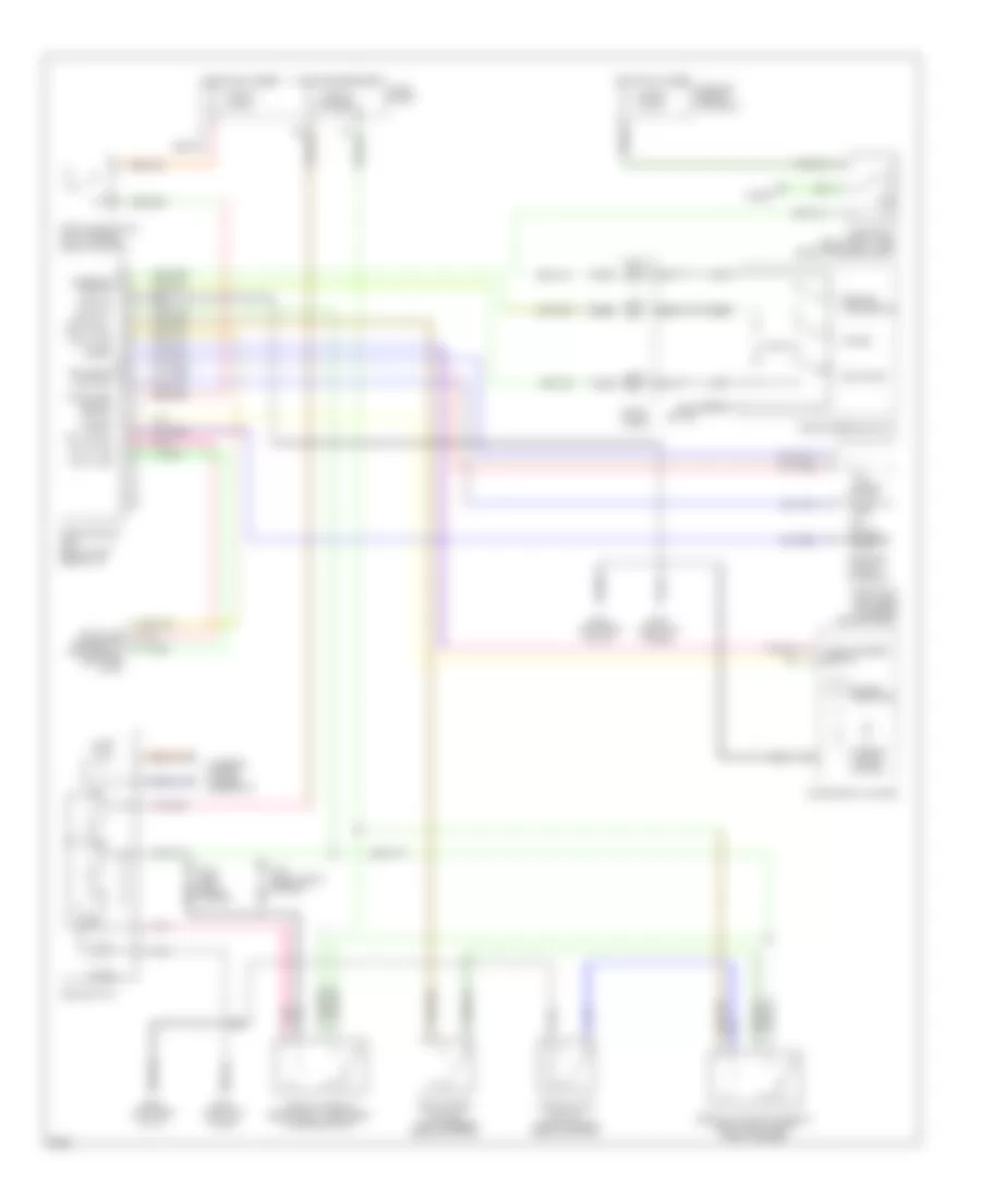
Электросхема системы круизконтроля, A/T для Infiniti I30 t 1997


Электросхема системы круизконтроля, A/T для Infiniti I30 t 1997 - Список элементов:
- A/t control unit (left kick panel)
- Act. cntrl
- Actuator control
- Air valve solenoid
- Ascd cancel switch (brake pedal support)
- Ascd control unit (below left side of i/p)
- Ascd hold relay (relay box 1, left front of engine compt)
- Ascd pump (left rear of engine compartment)
- Ascd steering switch
- Ascd sw.
- Ascd switch
- Cancel
- Crs. cancl
- Cruise
- Cruise indicator
- Cruise signal
- Data line
- Data link connector for consult (left side of i/p)
- Fuse 10 15 amp
- Fuse 12 7.5 amp
- Fuse 17 10 amp
- Fuse 64 15 amp
- Fuse and fusible link block
- Fuse block
- G100 (left front fender)
- G101 (right front fender)
- G120 (right side of engine)
- G202 (left side of i/p)
- G203 (left kick panel)
- Ground
- Horn relay (relay box 1, left front of engine compt)
- Horn switch
- Horns
- Hot at all times
- Hot in on or start
- Illum.
- Inhibitor relay (relay box 1, left front of engine compartment)
- Inhibitor switch (left side of transmission)
- Instrument cluster
- Interior lights system
- Interior lights system (rheostat)
- Nca
- Od cut signal
- Off
- On ind.
- Pnk
- Release valve solenoid
- Resume/ accelerate
- Set/coast
- Speed
- Spiral cable
- Steering switch
- Stop lamp switch (top of brake pedal support)
- Stop lamp switch od cut
- Theft warning relay 2 (relay box-2, right front fender)
- Vacuum motor
- Vehicle speed output
Электросхема системы круизконтроля, M/T для Infiniti I30 t 1997
Электросхема системы круизконтроля, M/T для Infiniti I30 t 1997 - Список элементов:
- Act. cntrl
- Actuator control
- Air valve solenoid
- Ascd cancel switch (top of brake pedal support)
- Ascd clutch switch (top of clutch pedal support)
- Ascd clutch switch relay (relay box 2, right front fender)
- Ascd control unit (below left side of i/p)
- Ascd hold relay (relay box 1, left front of engine compt)
- Ascd pump (left rear of engine compartment)
- Ascd steering switch
- Ascd sw.
- Ascd switch
- Cancel
- Crs. cancl
- Cruise
- Cruise indicator
- Data line
- Data link connector for consult (left side of i/p)
- Fuse 10 15 amp
- Fuse 12 7.5 amp
- Fuse 64 15 amp
- Fuse and fusible link block
- Fuse block
- G100 (left front fender)
- G101 (right front fender)
- G202 (left side of i/p)
- G203 (left kick panel)
- Ground
- Horn relay (relay box 1, left front of engine compt)
- Horn switch
- Horns
- Hot at all times
- Hot in on or start
- Illum.
- Instrument cluster
- Interior lights system
- Interior lights system (rheostat)
- Nca
- Off
- On ind.
- Pnk
- Release valve solenoid
- Resume/ accelerate
- Set/coast
- Speed
- Spiral cable
- Steering switch
- Stop lamp switch (top of brake pedal support)
- Stop lamp switch od cut
- Vacuum motor
- Vehicle speed output

 Čeština
 Dansk
Dansk Deutsch
 Ελληνικά
 English
 English
 Español
 Suomi
Suomi Français
 Français
 עברית
עברית Hrvatski
 Magyar
 Italiano
 日本語
日本語 한국어
한국어 Nederlands
 Polski
 Português
 Português
 Română
 Русский
 Slovenčina
 Slovenščina
 Türkçe
 中文 (中国)