СИСТЕМА ПЕРЕДАЧИ ДАННЫХ
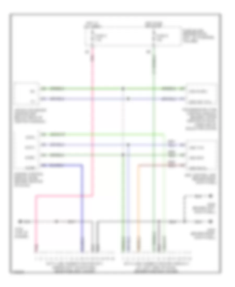
Электросхема компьютерной линии передачи данных CAN для Infiniti G20 1999
Электросхема компьютерной линии передачи данных CAN для Infiniti G20 1999 - Список элементов:
- Abs control unit (behind right kick panel)
- Abs diag l
- Abs rxd
- Abs txd
- Air bag diagnosis sensor unit (below rear of center console)
- Data link connector (for consult) (at left side of dash, behind fuse box cover)
- Data link connector (for gst) (under left dash panel, near fuse box cover)
- Engine control module (ecm) (behind center of dash)
- Fuse 5 7.5a
- Fuse 8 10a
- Fuse block (behind dash, left of steering column)
- G134 (top of engine)
- G200 (behind left kick panel)
- G203 (behind right kick panel)
- Hot at all times
- Hot in on or start
- Kline
- Pnk
- Scicl
- Scirx
- Scitx
- Sss in (rx)
- Sss out (tx)
- Transmission (tcm) control module (behind lower center of dash, forward of selector lever)
 Čeština
 Dansk
Dansk Deutsch
 Ελληνικά
 English
 English
 Español
 Suomi
Suomi Français
 Français
 עברית
עברית Hrvatski
 Magyar
 Italiano
 日本語
日本語 한국어
한국어 Nederlands
 Polski
 Português
 Português
 Română
 Русский
 Slovenčina
 Slovenščina
 Türkçe
 中文 (中国)
 Svenska