ANTI-LOCK BRAKES
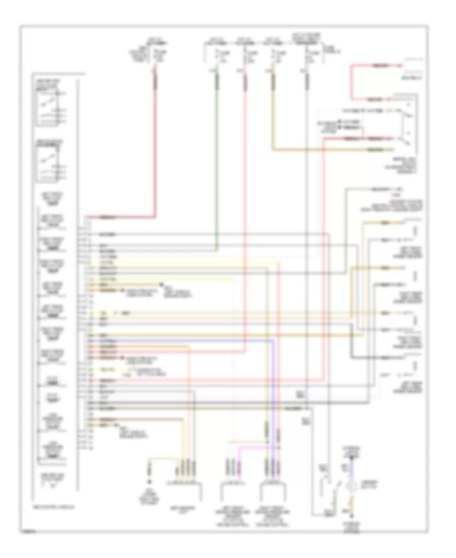
Anti-lock Brakes Wiring Diagram for Audi A6 Quattro 2008
List of elements for Anti-lock Brakes Wiring Diagram for Audi A6 Quattro 2008:
- Abs control module
- Abs control module fuse 1
- Abs return flow pump
- Abs return flow pump relay
- Abs solenoid valve relay
- Asr/esp button
- Brake light switch (on brake pedal assembly)
- Comfort system central control module (right rear of luggage compt)
- Computer data lines system
- Ecm relay
- Esp sensor unit
- Exterior lights system
- Fuse 10a
- Fuse 25a
- Fuse 40a
- Fuse 5a
- Fuse panel b
- G33 (under right end of dash)
- G671 (left side of engine compt)
- High pressure switch valve 1
- High pressure switch valve 2
- Hot at all times
- Information not available
- Interior lights system
- Left front abs inlet valve
- Left front abs outlet valve
- Left front abs wheel speed sensor
- Left front brake pressure sensor (w/ active cruise control)
- Left rear abs inlet valve
- Left rear abs outlet valve
- Left rear abs wheel speed sensor
- Pilot valve 1
- Pilot valve 2
- Right front abs inlet valve
- Right front abs outlet valve
- Right front abs wheel speed sensor
- Right front brake pressure sensor (w/ active cruise control)
- Right rear abs inlet valve
- Right rear abs outlet valve
- Right rear abs wheel speed sensor
- T10d
- T32d
 Čeština
 Dansk
Dansk Deutsch
 Ελληνικά
 English
 English
 Español
 Suomi
Suomi Français
 Français
 עברית
עברית Hrvatski
 Magyar
 Italiano
 日本語
日本語 한국어
한국어 Nederlands
 Polski
 Português
 Português
 Română
 Русский
 Slovenčina
 Slovenščina
 Türkçe
 中文 (中国)
 Svenska