Čeština
 Dansk
Dansk Deutsch
 Ελληνικά
 English
 English
 Español
 Suomi
Suomi Français
 Français
 עברית
עברית Hrvatski
 Magyar
 Italiano
 日本語
日本語 한국어
한국어 Nederlands
 Polski
 Português
 Português
 Română
 Русский
 Slovenčina
 Slovenščina
 Türkçe
 中文 (中国)

ANTI-LOCK BRAKES
Advanced Hydraulic Booster Wiring Diagram for Honda Civic LX 2010


List of elements for Advanced Hydraulic Booster Wiring Diagram for Honda Civic LX 2010:
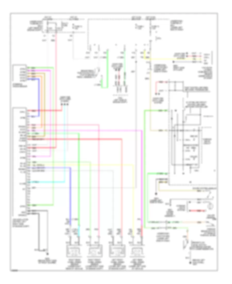
Anti-Lock Brakes Wiring Diagram, Except Hybrid with VSA for Honda Civic LX 2010
List of elements for Anti-Lock Brakes Wiring Diagram, Except Hybrid with VSA for Honda Civic LX 2010:
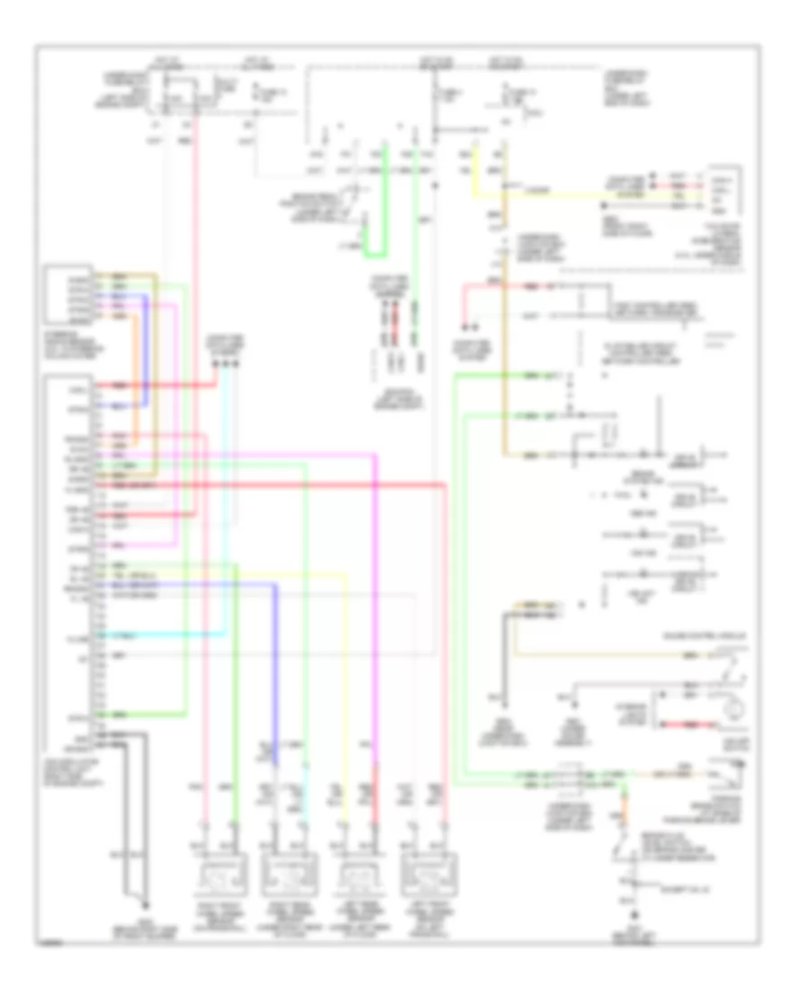
Anti-Lock Brakes Wiring Diagram, Except Hybrid without VSA for Honda Civic LX 2010
List of elements for Anti-Lock Brakes Wiring Diagram, Except Hybrid without VSA for Honda Civic LX 2010:
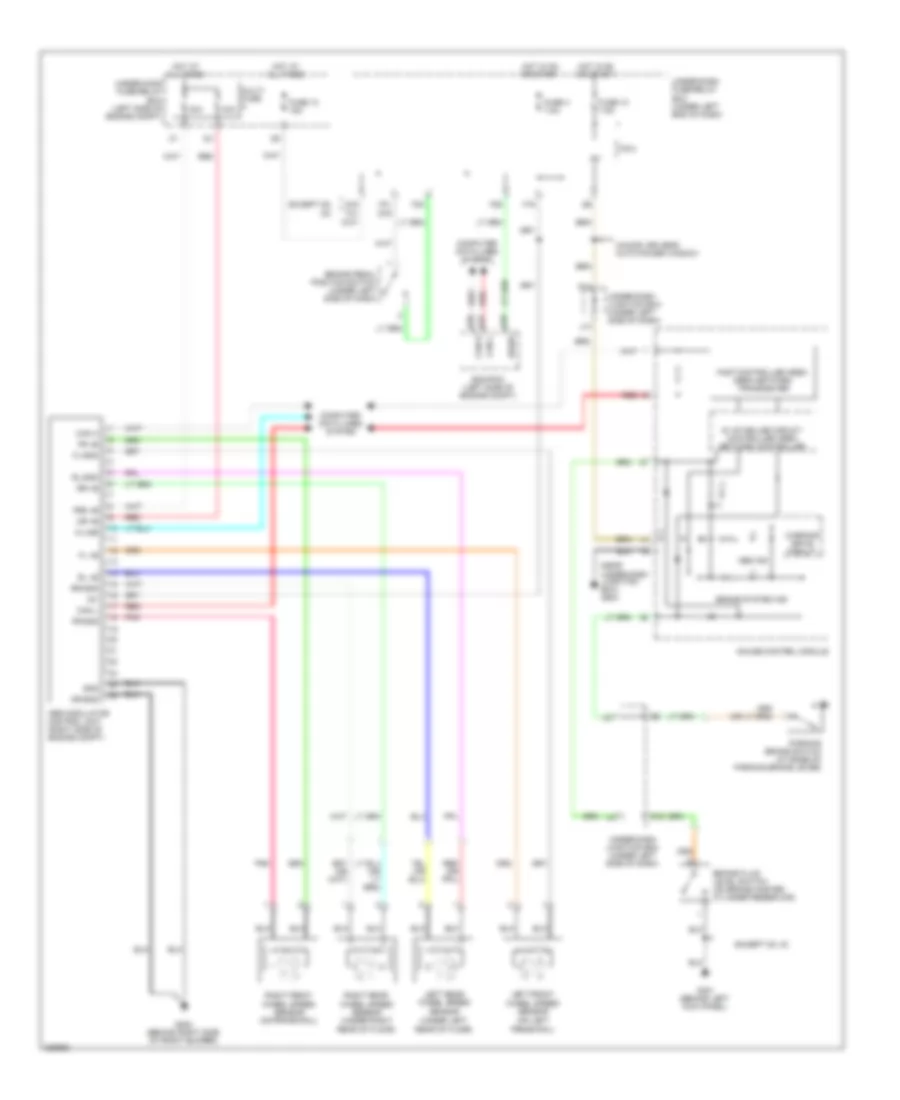
Anti-Lock Brakes Wiring Diagram, Hybrid for Honda Civic LX 2010
List of elements for Anti-Lock Brakes Wiring Diagram, Hybrid for Honda Civic LX 2010: