ANTI-LOCK BRAKES
Anti-lock Brakes Wiring Diagram (1 of 2) for Honda Ridgeline RTL 2007


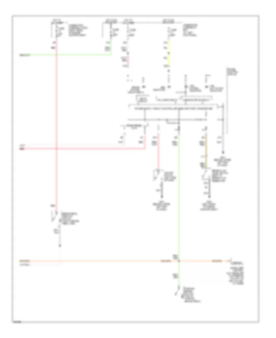
List of elements for Anti-lock Brakes Wiring Diagram (1 of 2) for Honda Ridgeline RTL 2007:
- (behind right kick panel)
- (left side of engine compartment)
- +b-fsr
- +b-mr
- A36
- Auxiliary under-hood fuse box (left rear of engine compartment)
- Bksw
- Can-h
- Can-l
- Computer data lines system
- Fl+b
- Fl-gnd
- Flp
- Fr+b
- Fr-gnd
- Frp
- Fuse 20a
- Fuse 40a
- G302 (behind left side of front bumper)
- Gnd
- Hot at all times
- Ig1
- J/c c451 (under middle of dash)
- K-line
- Left front wheel speed sensor (left side of engine compt)
- Left rear wheel speed sensor (under rear of vehicle)
- Parbrk
- Pnk
- Powertrain control (pcm) module (right rear of engine compartment)
- Red
- Right front wheel speed sensor (right side of engine compt)
- Right rear wheel speed sensor (under rear of vehicle)
- Rl+b
- Rl-gnd
- Rlp
- Rr+b
- Rr-gnd
- Rrp
- S-gnd
- Sgnd
- Steering angle sensor (in steering column)
- Vsa modulator control unit
- Vtm-4 control unit
- Yaw rate-lateral acceleration sensor (under center console)
Anti-lock Brakes Wiring Diagram (2 of 2) for Honda Ridgeline RTL 2007
List of elements for Anti-lock Brakes Wiring Diagram (2 of 2) for Honda Ridgeline RTL 2007:
- A10
- A19
- A20
- Abs indicator
- B14
- Brake fluid level switch (next to brake fluid reservoir)
- Brake pedal position switch (top of brake pedal arm)
- Brake system indicator
- Drive circuit
- F-can trans
- Fail safe circuit
- Fuse 20a
- Fuse 7.5a
- G301 (left front of engine compartment)
- G401 (behind upper left end of dash)
- Gauge control module
- H/brksw
- Hot at all times
- Hot in on or start
- Immobilizer control unit receiver (in steering column, on ignition key cylinder
- Parking brake switch (top of parking brake pedal)
- Red
- Under-dash fuse/relay box (at left kick panel)
- Under-hood fuse/relay box (right rear of engine compartment)
- Vsa system indicator
- Vsa activation indicator
- Vsa off switch (left side of dash)
- Warning drive circuit
- X16
- X34
- X35

 Čeština
 Dansk
Dansk Deutsch
 Ελληνικά
 English
 English
 Español
 Suomi
Suomi Français
 Français
 עברית
עברית Hrvatski
 Magyar
 Italiano
 日本語
日本語 한국어
한국어 Nederlands
 Polski
 Português
 Português
 Română
 Русский
 Slovenčina
 Slovenščina
 Türkçe
 中文 (中国)