Čeština
 Dansk
Dansk Deutsch
 Ελληνικά
 English
 English
 Español
 Suomi
Suomi Français
 Français
 עברית
עברית Hrvatski
 Magyar
 Italiano
 日本語
日本語 한국어
한국어 Nederlands
 Polski
 Português
 Português
 Română
 Русский
 Slovenčina
 Slovenščina
 Türkçe
 中文 (中国)

INSTRUMENT CLUSTER
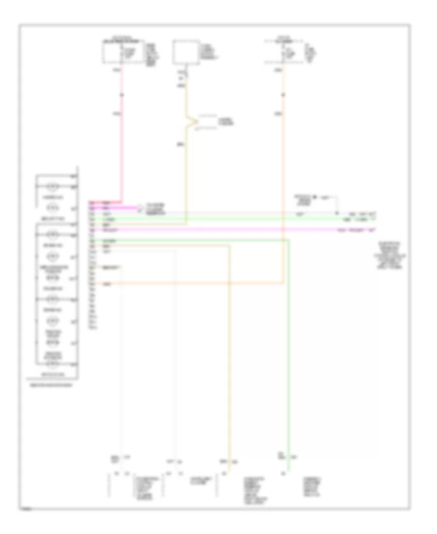
Driver Information Center Wiring Diagram for Oldsmobile Aurora 1995


List of elements for Driver Information Center Wiring Diagram for Oldsmobile Aurora 1995:
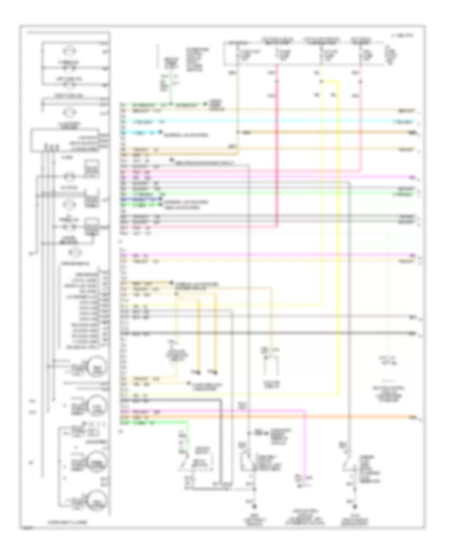
Instrument Cluster Wiring Diagram (1 of 2) for Oldsmobile Aurora 1995
List of elements for Instrument Cluster Wiring Diagram (1 of 2) for Oldsmobile Aurora 1995:
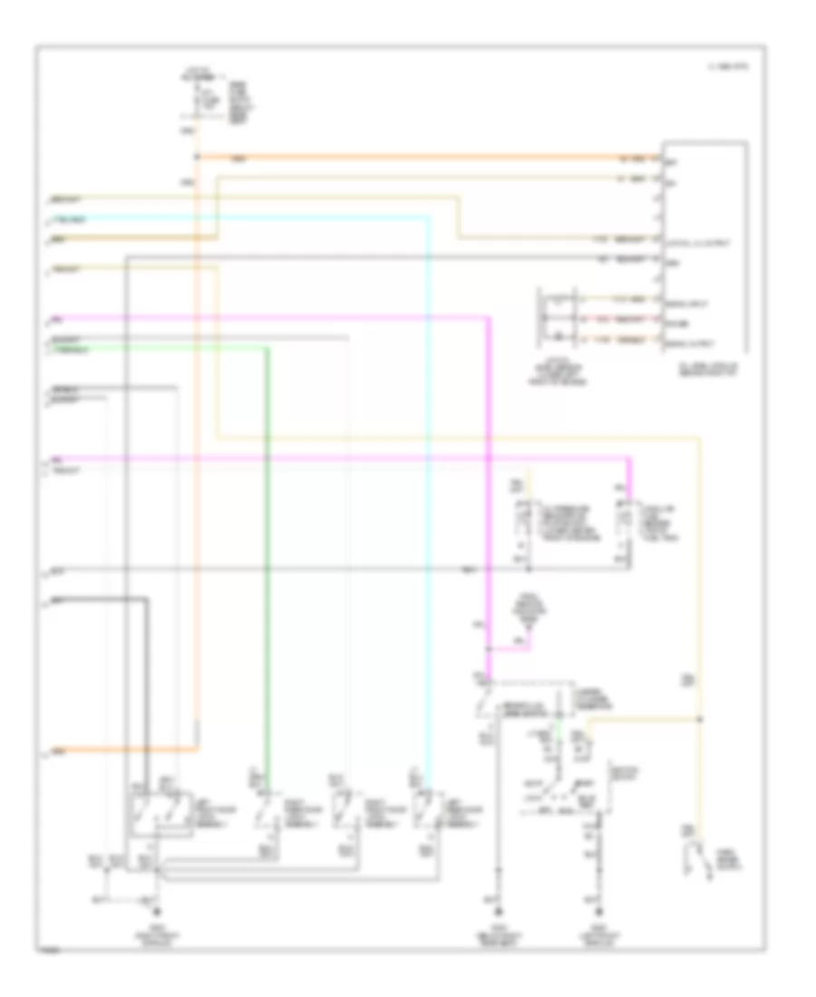
Instrument Cluster Wiring Diagram (2 of 2) for Oldsmobile Aurora 1995
List of elements for Instrument Cluster Wiring Diagram (2 of 2) for Oldsmobile Aurora 1995:
Remote Indicator Bank Wiring Diagram for Oldsmobile Aurora 1995
List of elements for Remote Indicator Bank Wiring Diagram for Oldsmobile Aurora 1995: