COMPUTER DATA LINES
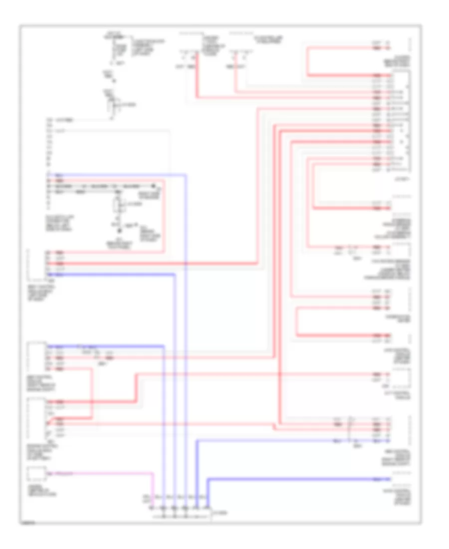
Computer Data Lines Wiring Diagram for Suzuki SX4 LE 2010
List of elements for Computer Data Lines Wiring Diagram for Suzuki SX4 LE 2010:
- (10ch)
- (center of vehicle floor)
- (if equipped)
- (in steering column assembly)
- (right side of engine)
- 4wd control module (center of dash)
- A/b sdm
- A/b sdm (center of vehicle floor)
- Abs control module (right rear of engine compt)
- Body control module (bcm) (left side of dash)
- C01
- C09
- Combination meter
- Cvt control module
- Dlc (data link connector) (below left side of dash)
- Dome fuse 15a
- E01
- E371
- E381
- E382
- Engine control module (ecm) (at side of battery)
- Esp control module (right rear of engine compt)
- G05
- G11 (behind right kick panel)
- G14 (behind right side of dash)
- G271
- G341
- Hot at all times
- Hvac control module (center of dash)
- Id controller
- J/c g308
- J/c g309
- J/c g311
- Junction block assembly (left side of dash)
- Kls ecm (behind right end of dash)
- Red
- Steering angle sensor (w/ esp)
- Yaw rate/g sensor (w/ esp) (under center console, below parking brake handle)
 Čeština
 Dansk
Dansk Deutsch
 Ελληνικά
 English
 English
 Español
 Suomi
Suomi Français
 Français
 עברית
עברית Hrvatski
 Magyar
 Italiano
 日本語
日本語 한국어
한국어 Nederlands
 Polski
 Português
 Português
 Română
 Русский
 Slovenčina
 Slovenščina
 Türkçe
 中文 (中国)
 Svenska