ENGINE PERFORMANCE
5.5L
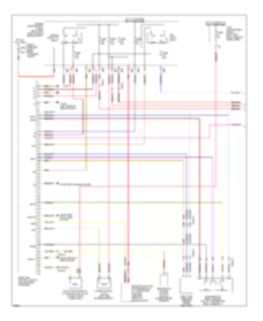
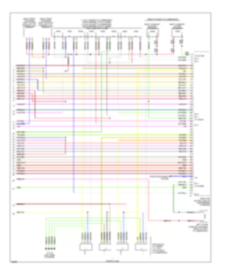
5.5L, Engine Performance Wiring Diagram (1 of 5) for Mercedes-Benz GL550 2012
List of elements for 5.5L, Engine Performance Wiring Diagram (1 of 5) for Mercedes-Benz GL550 2012:
- Accelerator pedal sensor (top of accelerator pedal assembly)
- Activated charcoal filter shutoff valve (in right rear wheelwell)
- Air pump relay
- Akf
- Can-c h
- Can-c l
- Computer data lines system
- Electric suction fan engine & a/c w/ integrated control (center front of engine compt)
- Engine circuit 87 relay
- Engine compartment fuse & relay box (right side of engine compt)
- Front prefuse (right rear of engine compt)
- Fuel tank pressure sensor (inside fuel tank)
- Fuse 100a
- Fuse 10a
- Fuse 15a
- Fuse 40a
- Fuse 5a
- Hot at all times
- Hot w/ circuit 15 relay energized
- Hot w/ starter relay energized
- Load compartment fuse & relay box (right rear of cargo area)
- Lues
- Me-sfi (me) control module (center rear of engine)
- Mr1
- Mr2
- Mr3
- Mr4
- Pnk
- Purge control valve (left side of engine compt)
- Red
- Restraints system control module (under center console)
- Slp
- Sp1m
- Sp1s
- Sp2m
- Sp2s
- Starting/charging system
- Usp1
- W16/3 (left rear of engine compt)
- X18/3-c1
- X25/2-c1
- X25/2-c2
- X26-c2
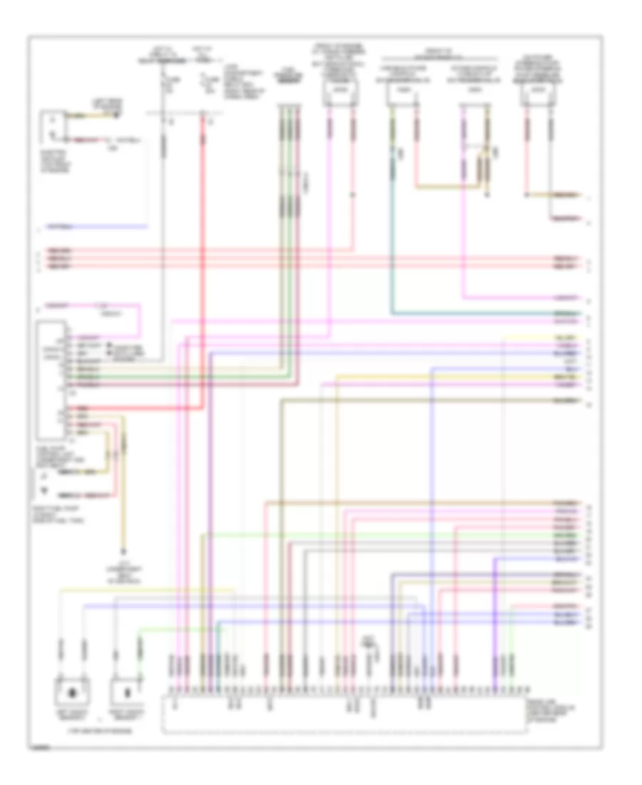
5.5L, Engine Performance Wiring Diagram (2 of 5) for Mercedes-Benz GL550 2012
List of elements for 5.5L, Engine Performance Wiring Diagram (2 of 5) for Mercedes-Benz GL550 2012:
- (+)
- (-)
- (front of engine) (w/ wiring harness installed but nonfuntional) three disk thermostat valve
- (front of intake manifold)
- (left rear of engine) w11w2
- (not used)
- (on power steering pump) power steering pump pressure regulator valve
- (top center of engine)
- Can-d h
- Can-d l
- Computer data lines system
- Dkp2
- Dks +
- Dks-s
- Electric air pump (top front of engine)
- Ev 7
- Fuel pressure sensor
- Fuel pump control unit (under right 2nd row seat)
- Fuse 20a
- Fuse 5a
- Hot at all times
- Hot w/ circuit 15 relay energized
- Intake manifold tumble flap switchover valve
- Ks-m
- Ks-s
- Kw out
- Left knock sensor 2
- Load compartment fuse & relay box (right rear of cargo area)
- Me-sfi (me) control module (center rear of engine)
- Nca
- Red
- Right fuel pump (in right side of fuel tank)
- Right knock sensor 1
- Variable intake manifold switchover valve
- W17 (under right seat of 2nd row)
- X18/3-c1
- X18/3-c4
- X205
- X25/2-c1
- X26
- X26-c1
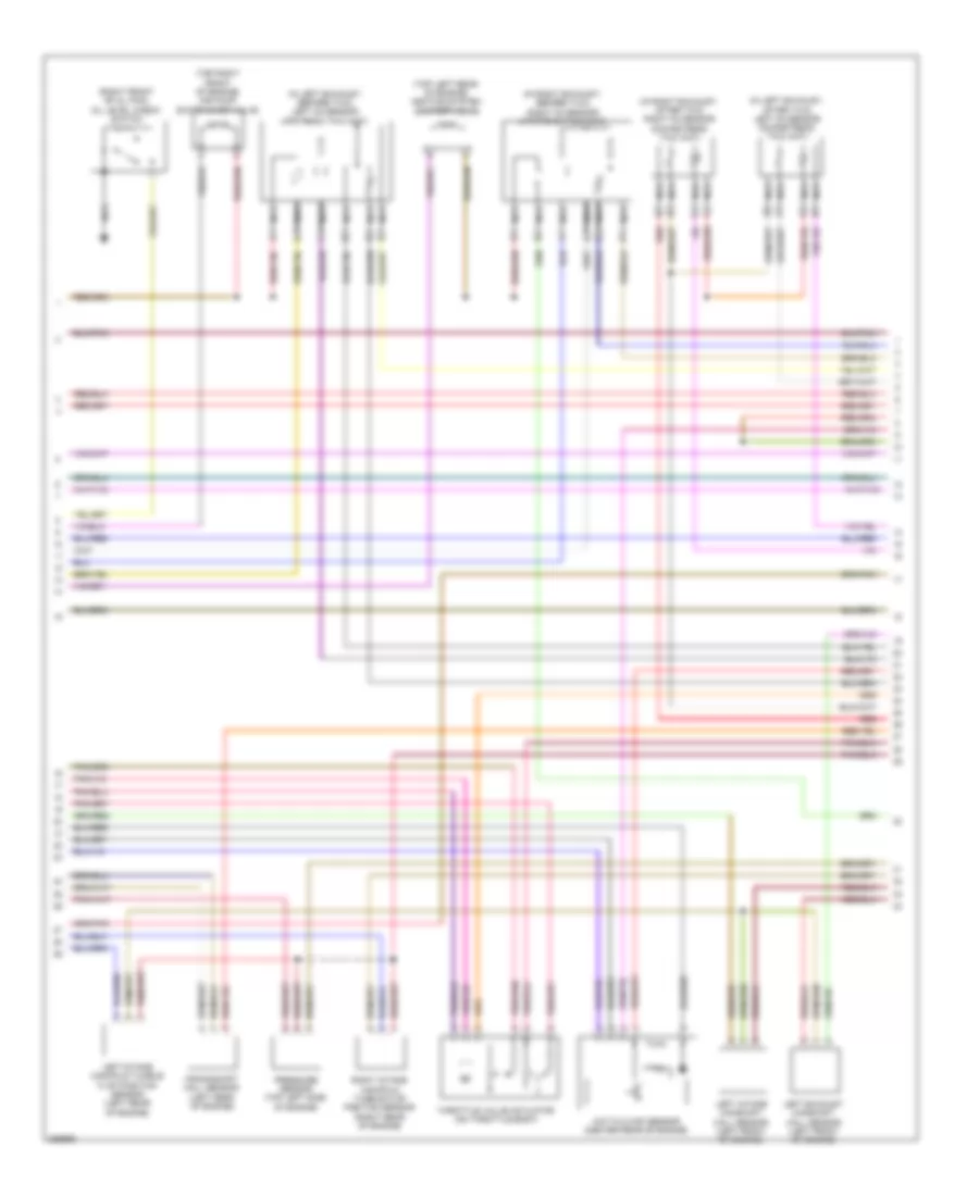
5.5L, Engine Performance Wiring Diagram (3 of 5) for Mercedes-Benz GL550 2012
List of elements for 5.5L, Engine Performance Wiring Diagram (3 of 5) for Mercedes-Benz GL550 2012:
- (in left exhaust, after twc) left o2 sensor downstream twc (kat)
- (in left exhaust, before twc) left o2 sensor upstream twc (kat)
- (in right exhaust, after twc) right o2 sensor downstream twc (kat)
- (in right exhaust, before twc) right o2 sensor upstream twc (kat)
- (right front of oil pan) oil level check switch
- (top left rear of engine) heating system shutoff valve
- (top right front of engine) air pump switchover valve
- Crankshaft hall sensor (left rear of engine)
- Hot film maf sensor (center rear of engine)
- Left exhaust camshaft hall sensor (left front of engine)
- Left intake camshaft hall sensor (left front of engine)
- Left intake manifold tumble flap position sensor (left rear of engine)
- Nca
- Pressure sensor (top left side of engine)
- Red
- Right intake manifold tumble flap position sensor (right rear of engine)
- Throttle valve actuator (on throttle body)
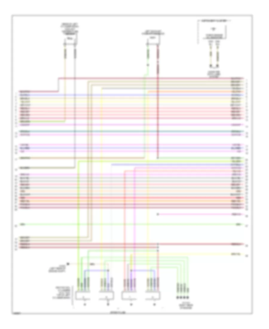
5.5L, Engine Performance Wiring Diagram (4 of 5) for Mercedes-Benz GL550 2012
List of elements for 5.5L, Engine Performance Wiring Diagram (4 of 5) for Mercedes-Benz GL550 2012:
- "check engine" mil indicator
- (rear of left cylinder bank) coolant temperature sensor
- Can- b h
- Can- b l
- Computer data lines system
- Ignition coil cylinders (5, 6, 7 & 8: top of left cylinder bank)
- Instrument cluster
- Left exhaust camshaft solenoid
- Red
- Spark plugs
- W11w1 (right rear of engine)
- W16/3 (left rear of engine compt)
5.5L, Engine Performance Wiring Diagram (5 of 5) for Mercedes-Benz GL550 2012
List of elements for 5.5L, Engine Performance Wiring Diagram (5 of 5) for Mercedes-Benz GL550 2012:
- (1, 2 & 3: on right cylinder bank, above respective cylinder) (4, 5 & 6: on left cylinder bank, above respective cylinder) fuel injector valves
- (front of right cylinder bank)
- (right front of engine) right exhaust camshaft hall sensor
- (right front of engine) right intake camshaft hall sensor
- At nw se1
- At nwsa1
- At nwse2
- Ev 1
- Ev 2
- Ev 3
- Ev 4
- Ev 5
- Ev 6
- Ev 8
- Ignition coil cylinders (1, 2, 3 & 4: top of right cylinder bank)
- Left intake camshaft solenoid (front of left cylinder bank)
- Lin
- Me-sfi (me) control module center rear of engine)
- Red
- Red/
- Right camshaft exhaust solenoid
- Right camshaft intake solenoid
- Spark plugs
- Starting/charging system
- W11w2 (left rear of engine)

 Čeština
 Dansk
Dansk Deutsch
 Ελληνικά
 English
 English
 Español
 Suomi
Suomi Français
 Français
 עברית
עברית Hrvatski
 Magyar
 Italiano
 日本語
日本語 한국어
한국어 Nederlands
 Polski
 Português
 Português
 Română
 Русский
 Slovenčina
 Slovenščina
 Türkçe
 中文 (中国)