POWER DISTRIBUTION
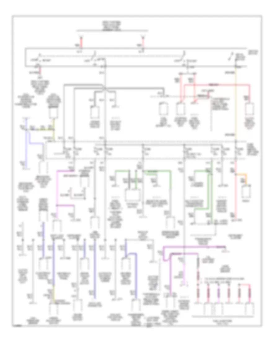
Power Distribution Wiring Diagram (1 of 3) for Volkswagen Golf GLS 2005
 https://portal-diagnostov.com/license.html
Automotive Electricians Portal FZCO
Automotive Electricians Portal FZCO
https://portal-diagnostov.com/license.html
https://portal-diagnostov.com/license.html
Automotive Electricians Portal FZCO
Automotive Electricians Portal FZCO
List of elements for Power Distribution Wiring Diagram (1 of 3) for Volkswagen Golf GLS 2005:
- (2.0l, 3.2l) (others)
- (late prod 2004, 2005) (early prod 2004)
- 1.8l, 2.0l 2.8l, 3.2l
- 12v socket
- 16a
- 28a
- 30a
- 31a
- 33a
- 35a
- 36a
- 37a
- 44a
- 75x
- Abs control module
- Alarm system & anti- theft fuse
- All-wheel drive control module (r32)
- Battery
- Brake system vacuum pump (1.8l, 2.0l)
- Brake vacuum pump fuse 20a
- Central locking/ anti-theft warning system fuse
- Circuit breaker 30a
- Climatronic control module (2.8l, 3.2l)
- Comfort system central control module
- Coolant fan control module
- Coolant fan control module (2.8l, 3.2l)
- Coolant fan control thermal switch
- Coolant preheating relay (high heat outlet) (1.9l)
- Coolant preheating relay (low heat outlet) (1.9l)
- Diesel direct fuel injection (dfi) engine control module
- Driver's heated seat control module
- Driver's side door control module
- Dual horn relay
- Fuel pump relay (2004 early production)
- Fuel pump relay (except 1.9l)
- Fuse 10a
- Fuse 110a
- Fuse 110a 150a
- Fuse 15a
- Fuse 20a
- Fuse 30a
- Fuse 30a (or 40a)
- Fuse 37 20a 30a
- Fuse 40a
- Fuse 50a
- Fuse 5a
- Fuse bracket/ battery (behind battery)
- Fuse panel (behind left side of dash)
- G42 (below left side of dash)
- G50 (left front of luggage compt)
- Generator
- Glow plug triggering control module (1.9l)
- Headlight dimmer/ flasher switch
- Left rear door control module
- Light switch
- Load reduction relay
- Memory seat control module
- Motronic engine control module (ecm)
- Multi-function steering wheel control module
- Park/ neutral position relay
- Passenger's heated seat control module
- Passenger's seat switch
- Passenger's side door control module
- Power memory seat circuit breaker (in relay panel)
- Power sunroof control module
- Power window circuit breaker (in relay panel)
- Red
- Red red
- Relay panel (under left side of dash)
- Right rear door control module
- Secondary air injection pump relay (except 1.9l)
- Starter
- T14
- T15
- T16a
- T2b
- T4a
- T60 t121
- T6f
- T8f
- Thirteen -fold auxiliary relay panel
- Thirteen -fold auxiliary relay panel (under left side of dash)
- To fuse panel (diagram 3 of 3)
- To ignition switch (diagram 2 of 3)
- Wiper/ washer intermittent relay
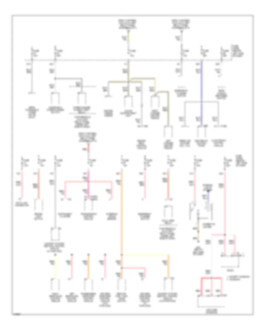
Power Distribution Wiring Diagram (2 of 3) for Volkswagen Golf GLS 2005
List of elements for Power Distribution Wiring Diagram (2 of 3) for Volkswagen Golf GLS 2005:
- (1.9l)
- (2.8l) evaporative emission canister purge regulator valve
- (2.8l) positive crankcase ventilation heating element
- (4-spd)
- (4-spd) (5-spd)
- (5-spd)
- (canada) (exc canada)
- (exc 1.9l)
- (not used)
- 1.8l & 2.0l engine code avh & azg
- 1.9l late prod 2004, 2005
- 10a
- 11a
- 2004, 2005
- 29a
- 3.2l, 2.0l bev, 2.0l bbw
- 31a
- 34a
- 50b
- 75x
- 86s
- A/t
- Abs control module
- Air bag control module
- Airbag spiral spring/ return spring
- Anti-slip control switch (w/ asc)
- Automatic day/night interior mirror
- Back-up light switch (m/t)
- Brake vacuum vent valve switch
- Climatronic control module
- Clutch pedal position switch (m/t)
- Clutch vacuum vent valve switch (m/t)
- Comfort system central control module
- Coolant fan control module
- Cruise control switch
- Data link connector
- Daytime running lights change -over relay
- Diesel direct fuel injection (dfi) engine control module (ecm) (1.9l)
- Driver's heated seat control module
- Early prod
- Esp switch
- From thirteen -fold auxiliary relay panel (diagram 1 of 3)
- From thirteen -fold auxiliary relay panel (splice) (diagram 1 of 3)
- Fuel injectors (2.8l, 3.2l)
- Fuel pump relay (except 1.9l)
- Fuse 10a
- Fuse 10a (2.8l)
- Fuse 15a
- Fuse 20a
- Fuse 5a
- Fuse 7.5a
- Fuse panel (behind left side of dash)
- Heater-a/c control panel
- High pressure sensor
- Ignition switch
- Instrument cluster
- Key-in ignition switch
- Late prod
- Lock
- M/t
- Mass air flow sensor
- Mirror adjustment switch
- Motronic engine control module
- Multi- function steering wheel control module
- Multi-function transmission range switch
- Nca
- Park neutral position relay (a/t)
- Park/ neutral position relay
- Passenger's heated seat control module
- Radio
- Red
- Secondary air injection pump relay (2.8l)
- Secondary air injection solenoid valve (2.8l)
- Selector lever position warning light (p/n)
- Shift lock solenoid
- Speedometer vehicle speed sensor
- Start
- Starting interlock relay (m/t)
- Steering angle sensor
- T14
- T16a
- T23
- T32
- T68 t68a
- T8b
- T94 t121
- Thirteen -fold auxiliary relay panel (under left side of dash)
- Thirteenfold auxiliary relay panel (under left side of dash)
- Tiptronic switch
- Transmission control module
Power Distribution Wiring Diagram (3 of 3) for Volkswagen Golf GLS 2005
List of elements for Power Distribution Wiring Diagram (3 of 3) for Volkswagen Golf GLS 2005:
- (4-spd)
- (5-spd)
- 12a
- 13a
- 14a
- 15a
- 24a
- 25a
- 26a
- 27a
- 38a
- 39a
- 40a
- 41a
- 42a
- Amplifier (monsoon)
- Brake- light switch
- Cigarette lighter
- Climatronic control module
- Comfort system central control module (w/ pwr wdo)
- Comfort system central control module (w/o pwr wdo)
- Data link connector
- Driver's side door control module (w/ pwr wdo)
- Driver's side door control module (w/o pwr wdo)
- Dual horn relay
- Emergency flasher switch
- Except monsoon
- Fresh air blower (2.8l, 3.2l)
- From thirteen- fold auxiliary relay panel (diagram 1 of 3)
- Fuse 10a
- Fuse 15a
- Fuse 20a
- Fuse 25a
- Fuse 5a
- Fuse 7.5a
- Fuse panel (behind left side of dash)
- G42 (below left side of dash)
- Glove compartment light
- Heated mirror mirror
- Heater-a/c control panel
- Instrument cluster
- Interior lights system
- Left rear door control module
- Left washer heater nozzle
- Memory seat control module
- Monsoon
- Passenger's side door control module
- Radio
- Rear window defogger switch
- Rear windshield wiper motor (golf)
- Red
- Remote/ fuel tank door switch
- Right rear door control module
- Right washer heater nozzle
- Steering angle sensor
- T16b
- T23
- T28
- T32
- T6d
- T8 t16d
- Thirteenfold auxiliary relay panel (under left side of dash)
- Transmission control module
- Windshield wiper/washer switch
- Wiper/washer intermittent relay

 Čeština
 Dansk
Dansk Deutsch
 Ελληνικά
 English
 English
 Español
 Suomi
Suomi Français
 Français
 עברית
עברית Hrvatski
 Magyar
 Italiano
 日本語
日本語 한국어
한국어 Nederlands
 Polski
 Português
 Português
 Română
 Русский
 Slovenčina
 Slovenščina
 Türkçe
 中文 (中国)