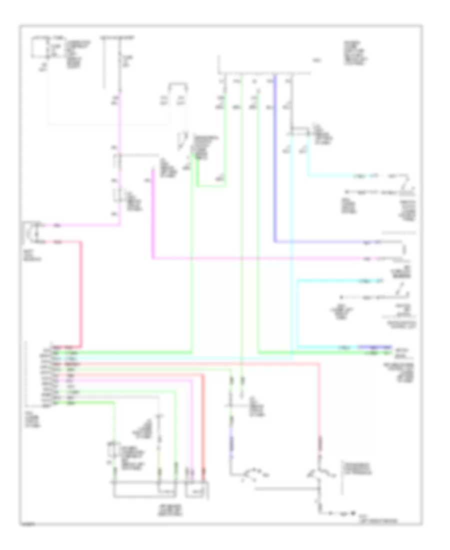
SHIFT INTERLOCK
Shift Interlock Wiring Diagram for Acura RL 2005
List of elements for Shift Interlock Wiring Diagram for Acura RL 2005:
- A11
- A13
- App sensor (under left side of dash)
- Apsa
- Apsb
- Atp-n
- Atp-p
- B-can
- B23
- Bksw
- Brake pedal position switch (near brake pedal)
- D13
- D14
- Driver's under- dash fuse/ relay box (behind left lick panel)
- Driver's under-dash fuse/relay box (behind left kick panel)
- E12
- E22
- Fuse 15a
- Fuse 20a
- G101 (left side of engine)
- G501 (under left side of dash)
- G503 (under middle of dash)
- Hot at all times
- Hot in on or start
- Ignition key switch
- Ignition switch control unit
- J/c c507 (behind left side of dash)
- J/c c508 (behind left side of dash)
- J/c c517 (behind middle of dash)
- J/c c523 (behind middle of dash)
- J/c c525 (under right side of dash)
- Key interlock solenoid
- Key sw
- Keyless access control unit (under left side of dash)
- Micu
- N26
- P-pin
- P15
- P16
- Park pin switch (under console panel)
- Pcm (under middle of dash)
- Pnk
- Red
- Sg3
- Sg4
- Shift lock solenoid
- Sls
- Transmission range switch (on transaxle)
- Under-hood fuse/relay box (left rear of engine compt)
- Vcc3
- Vcc4
- X10
- X18
- X38
 Čeština
 Dansk
Dansk Deutsch
 Ελληνικά
 English
 English
 Español
 Suomi
Suomi Français
 Français
 עברית
עברית Hrvatski
 Magyar
 Italiano
 日本語
日本語 한국어
한국어 Nederlands
 Polski
 Português
 Português
 Română
 Русский
 Slovenčina
 Slovenščina
 Türkçe
 中文 (中国)
 Svenska