AUTOMOTIVE ELECTRICIANS PORTAL

WARNING SYSTEMS – Acura RDX 2013 – SYSTEM WIRING DIAGRAMS

WARNING SYSTEMS

Chime Wiring Diagram for Acura RDX 2013

Chime Wiring Diagram for Acura RDX 2013 https://portal-diagnostov.com/license.html
https://portal-diagnostov.com/license.html Automotive Electricians Portal FZCO Automotive Electricians Portal FZCO
Download PDF file

List of elements for Chime Wiring Diagram for Acura RDX 2013:

  • 0=off 1=park 2=auto 3=head
  • 5v control circuit
  • A11
  • A20
  • A21
  • Amplifier
  • B22
  • B24
  • B32
  • B33
  • B34
  • B40
  • Brake fluid level switch (in brake master cylinder)
  • Brake system ind
  • C104
  • C106
  • C111
  • C114
  • C128
  • C130
  • C144
  • C145
  • C147
  • C148
  • Center junction box 2
  • Combination light switch
  • Compulsory turning-on circuit
  • Computer data
  • Computer data lines system
  • Cruise light dimming circuit
  • D17
  • Door ind
  • Driver's door switch
  • Driver's seat belt buckle switch
  • Front passenger's door switch
  • Front passenger's seat belt buckle switch
  • Fuse 10a
  • Fuse 7.5a
  • G302 (below air filter assembly)
  • G502 (near steering column)
  • G601 (left rear wheel well)
  • G602 (upper left "d" pillar)
  • G701 (below left front seat)
  • G702 (below right front seat)
  • Gauge control module
  • H b-can
  • Headlight switch
  • Hot at all times
  • Hot in on or start
  • Indicator drive circuit
  • J/c c008 (below multi-information display unit)
  • L b-can
  • Left rear door switch
  • Lights on ind
  • Lines system
  • Micu
  • N11
  • Parking brake switch (parking brake pedal assembly)
  • Pnk
  • Power tailgate closer unit (center of tailgate)
  • Power tailgate control unit (left side of cargo area)
  • Q16
  • Red
  • Right rear door switch
  • Seat belt reminder ind
  • Speaker
  • Srs unit
  • Sw 5v
  • Tailgate latch switch/ tailgate release actuator
  • Transceiver b-can
  • Under-dash fuse/relay box (behind left side of dash)
  • Under-hood fuse/relay box (left rear of engine compt)
  • W/ power tailgate
  • W/o power tailgate

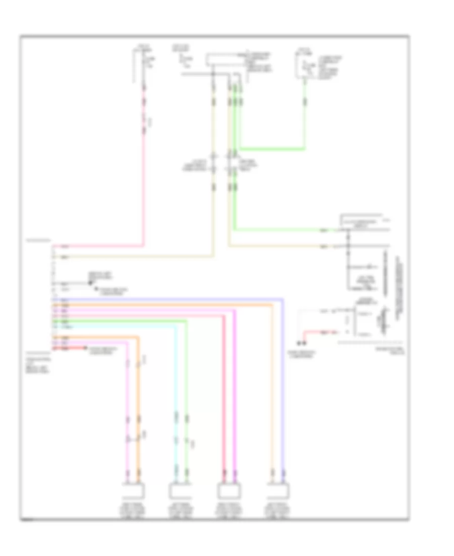
Tire Pressure Monitoring Wiring Diagram for Acura RDX 2013

Tire Pressure Monitoring Wiring Diagram for Acura RDX 2013 https://portal-diagnostov.com/license.html
https://portal-diagnostov.com/license.html Automotive Electricians Portal FZCO Automotive Electricians Portal FZCO
Få åtkomst till alla kopplingsscheman bilDownload PDF file

List of elements for Tire Pressure Monitoring Wiring Diagram for Acura RDX 2013:

  • (behind left side of dash) g401
  • C104
  • C114
  • C125
  • C36
  • Center junction box 2
  • Computer data lines system
  • D17
  • F-can h
  • F-can l
  • Fuse 10a
  • Fuse 7.5a
  • Gauge control module
  • Hot at all times
  • Hot in on or start
  • Indicator drive circuit
  • J/c c018 (near front wiper motor)
  • Left front tpms initiator (at left front wheel well)
  • Left rear tpms initiator (at left rear wheel well)
  • Low tire pressure ind
  • Multi-information display
  • Pnk
  • Q16
  • Red
  • Right front tpms initiator (at right front wheel well)
  • Right rear tpms initiator (at right rear wheel well)
  • System message ind
  • Tpms control unit (below left side of dash)
  • Transceiver f-can
  • Under-dash micu fuse/relay box (behind left side of dash)
  • Under-hood fuse/relay box (left rear of engine compt)