ANTI-LOCK BRAKES
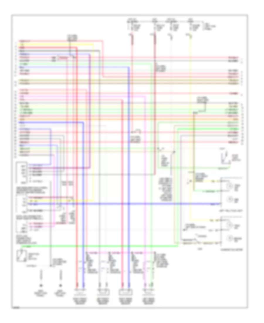
Anti-lock Brake Wiring Diagrams, with Traction Control (1 of 3) for Toyota Supra 1996
 https://portal-diagnostov.com/license.html
Automotive Electricians Portal FZCO
Automotive Electricians Portal FZCO
https://portal-diagnostov.com/license.html
https://portal-diagnostov.com/license.html
Automotive Electricians Portal FZCO
Automotive Electricians Portal FZCO
List of elements for Anti-lock Brake Wiring Diagrams, with Traction Control (1 of 3) for Toyota Supra 1996:
- (1996) i18
- (eng harn, above radiator)
- (eng harn, left front fender apron)
- (eng harn, near air box)
- (eng harn, right front fender)
- (i/p harn, top center of dash)
- (i/p harn, top right end of dash)
- A10
- A11
- A12
- A13
- A14
- A15
- A16
- A17
- A18
- A19
- A20
- A21
- A22
- A23
- A24
- A25
- A26
- Abs 1 fuse 60a
- Abs 2 fuse 30a
- Abs actuator (lower right rear of engine compartment)
- Abs and traction ecu (behind center console)
- Abs motor relay (r/b 5, right side of engine compartment)
- Abs solenoid relay (r/b 5, right side of eng compt)
- Abso
- Ast
- B10
- B11
- B12
- B13
- B14
- B15
- B16
- Bat
- Brc
- Brfa
- Brp
- C10
- C11
- C12
- D/g
- E2(1995) e6(1996)
- Exo
- Fl+
- Fl-
- Flo
- Fr+
- Fr-
- Fro
- G100 (left front fender)
- G101 (right front fender)
- G203 (right kick panel)
- Gnd
- Gs1
- Gs2
- Gst
- Hot at all times
- I11
- I18
- Ig1
- Lbl
- Mtt
- Pnk
- R/b 2 (left side of engine compartment)
- Red
- Rl+
- Rl-
- Rld
- Rr+
- Rr-
- Rro
- Sfl
- Sfr
- Smc
- Src
- Srl
- Srr
- Stp
- Thfa
- Tmr
- Traction brake actuator (left rear of engine compartment)
- Traction motor relay (r/b 5, right side of engine compartment)
- Traction pump/ motor (left rear of engine compartment)
- Traction solenoid relay (r/b 5, right side of eng compt)
- Trco
- Tsr
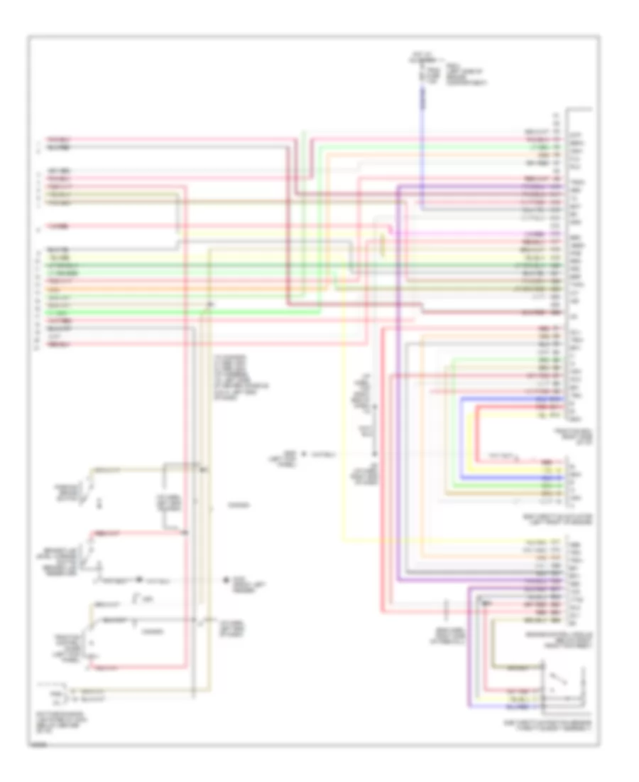
Anti-lock Brake Wiring Diagrams, with Traction Control (2 of 3) for Toyota Supra 1996
List of elements for Anti-lock Brake Wiring Diagrams, with Traction Control (2 of 3) for Toyota Supra 1996:
- (i/p harn, left end of dash)
- (i/p harn, left end of dash) i2
- (i/p harn, left front fender apron)
- (i/p harn, right end of dash)
- (i/p harn, top center of dash) i11
- (usa i995) i2 (usa 1996) i9 (canada) i10 (i/p harn, i2: left end of dash; i9 & i10: left side of center console)
- +ig
- Abs
- Abs deceleration/lateral acceleration sensor (below center console)
- Abs ind
- Brake ind
- Canada
- Combination meter
- Data link connector 1 (right side of firewall)
- Data link connector 2 (left side of steering column)
- Ecu-1g fuse 10a
- Ecu-b fuse 10a
- G200 (left kick panel)
- G203 (right kick panel)
- Gauge fuse 10a
- Gnd
- Gs1
- Gs2
- Gst
- Hot at all times
- Hot in on
- I10 (1996) i9 (1995) (i/p harn, left side shield
- I20
- I4 (i/p harn, left end of dash)
- I9 (i/p harn, shield left side of center console)
- J/b 1 (left kick panel)
- Left front abs speed sensor
- Left rear abs speed sensor
- Left telltale light
- Of center console)
- Pnk
- Red
- Right front abs speed sensor
- Right rear abs speed sensor
- Stop fuse 15a
- Stop light switch
- Trac ind
- Trac off ind
- Traction off switch
- Trc
- Usa
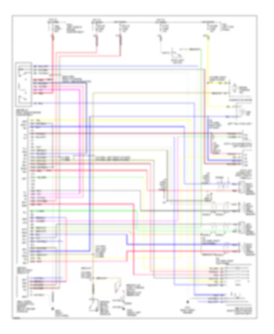
Anti-lock Brake Wiring Diagrams, with Traction Control (3 of 3) for Toyota Supra 1996
List of elements for Anti-lock Brake Wiring Diagrams, with Traction Control (3 of 3) for Toyota Supra 1996:
- (eng harn, right side of firewall)
- (i/p harn, left end of dash)
- (i/p harn, top right end of dash) i18
- A10
- A11
- A12
- A13
- A14
- A15
- A16
- A17
- A18
- A19
- A20
- A21
- A22
- A23
- A24
- A25
- A26
- A27
- A38
- Abs
- Abso
- Acm
- B10
- B11
- B12
- B41
- B42
- B63
- B64
- B65
- Bat
- Bcm
- Brake fluid level warning switch (brake fluid reservoir)
- Brc
- Brfa
- Brp
- Canada
- Csw
- Daytime running lights relay maim (below center of i/p)
- E16
- Efi+
- Efi-
- Engine control module (below right front footrest)
- Flo
- Fro
- G100 (front left fender)
- G200 (left kick panel)
- Gnd
- Hot at all times
- I10 (canada) i4 (1995 usa) i2 (1996 usa) (i/p harness, i10: left side of center console; i2 & i4: left end of dash)
- I20 (i/p harn, right end of dash)
- Idl1
- Idl2
- Ig1
- Ind
- Neo
- Oil
- Parking brake switch
- Pkb
- R/b 2 (left side of engine compartment)
- Red
- Rlo
- Rro
- Stp
- Sub throttle actuator (left front of engine)
- Sub throttle position sensor (throttle body assembly)
- Thfa
- Trac fuse 7.5a
- Traction control diode (left kick panel)
- Traction ecu (right side of i/p)
- Trc+
- Trc-
- Trco
- Usa
- Vcc
- Vta2
Anti-lock Brake Wiring Diagrams, without Traction Control for Toyota Supra 1996
List of elements for Anti-lock Brake Wiring Diagrams, without Traction Control for Toyota Supra 1996:
- (eng harn, front of engine compt, above radiator)
- (i/p harn, left end of dash)
- (i/p harn, left end of dash) i2
- (i/p harn, left end of dash) i4 (1995) i2 (1996)
- (i/p harn, left front of dash) (i/p harn, left rear of dash)
- (i/p harn, right kick panel)
- A10
- A11
- A12
- A13
- A14
- A15
- A16
- A17
- A18
- A19
- A20
- A21
- A22
- A23
- A24
- A25
- A26
- Abs actuator (right side of engine compartment)
- Abs ecu (below right side of i/p)
- Abs fuse 1 60a
- Abs ind
- Abs lateral acceleration sensor (below center console)
- Abs relay (right side of engine compartment)
- Ast
- B10
- B11
- B12
- B13
- B14
- B15
- B16
- Bat
- Brake fluid level warning switch (brake fluid reservoir)
- Brake warning ind
- Combination meter
- D/g
- Data link connector 1 (right side of firewall)
- Data link connector 2 (left side of i/p)
- E18
- E9/e21
- Ecu-b fuse 10a
- Ecu-ig fuse 10a
- Fl+
- Fl-
- Fr+
- Fr-
- Fss
- G100 (front left fender)
- G101 (right front fender)
- G203 (right kick panel)
- Gauge fuse 10a
- Gnd
- Gnd1
- Gnd2
- Gs1
- Gs2
- Gst
- Hot at all times
- Hot in run
- I/p harn, right side of dash) i14
- I20 (i/p harn, right end of dash)
- I22
- I22 (i/p harn, right kick panel)
- I5 (1995) i4 (1996)
- Ig1
- J/b 1 (left kick panel)
- Left front abs speed sensor
- Left rear abs speed sensor
- Left telltale light
- Parking brake switch (below center console)
- Pkb
- Pnk
- R/b 2 (left side of engine compartment)
- Red
- Right front abs speed sensor
- Right rear abs speed sensor
- Rl+
- Rl-
- Rr+
- Rr-
- Rss
- Sfl
- Sfr
- Shield
- Srl
- Srr
- Stop fuse 15a
- Stop light switch
- Stp

 Čeština
 Dansk
Dansk Deutsch
 Ελληνικά
 English
 English
 Español
 Suomi
Suomi Français
 Français
 עברית
עברית Hrvatski
 Magyar
 Italiano
 日本語
日本語 한국어
한국어 Nederlands
 Polski
 Português
 Português
 Română
 Русский
 Slovenčina
 Slovenščina
 Türkçe
 中文 (中国)