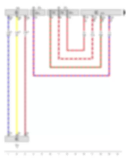
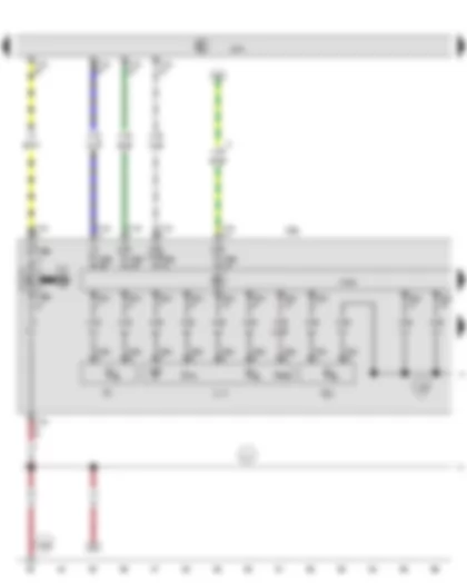
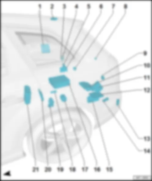
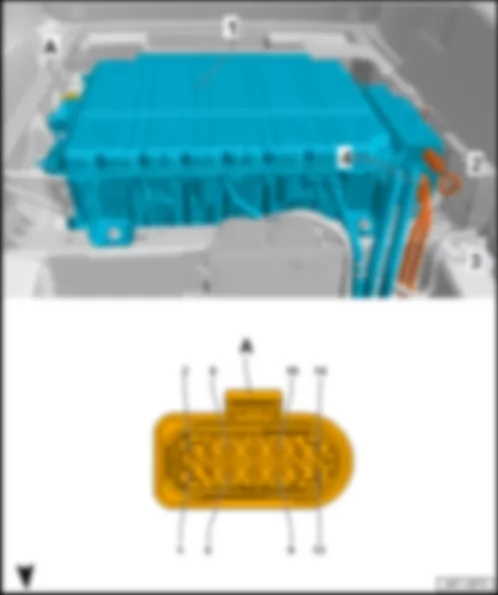
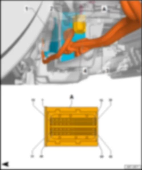
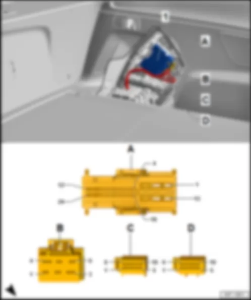
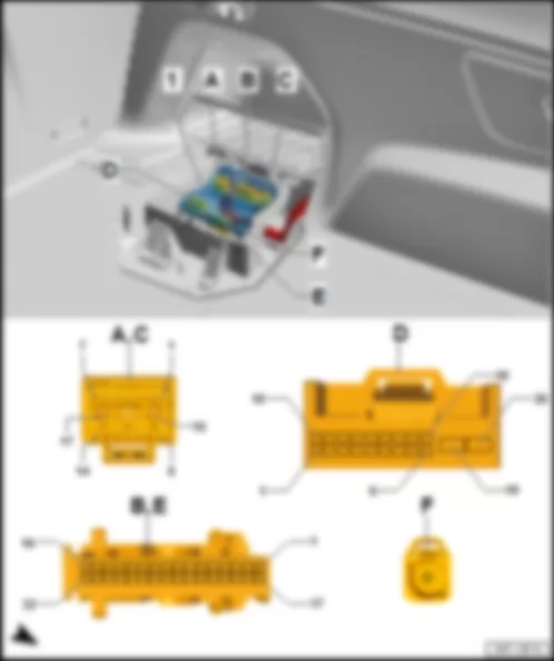
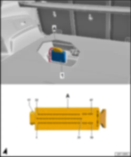
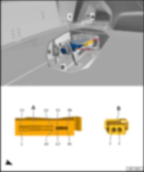
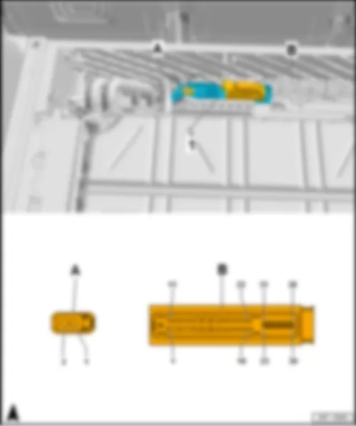
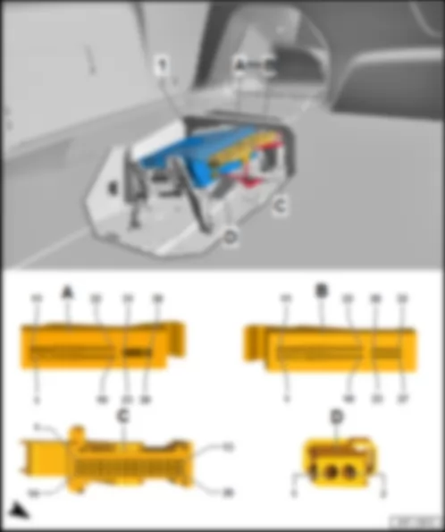
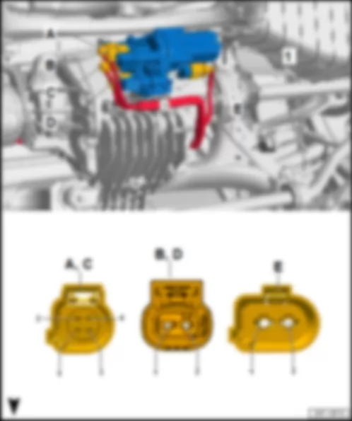
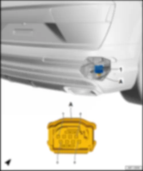
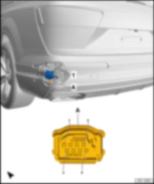
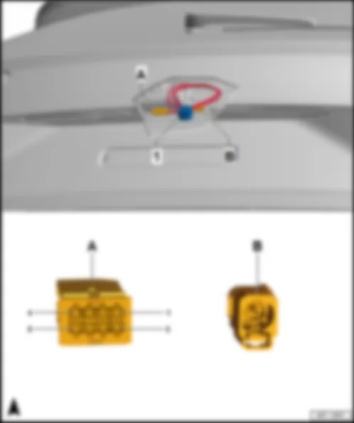
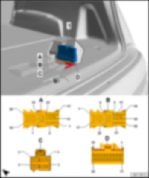
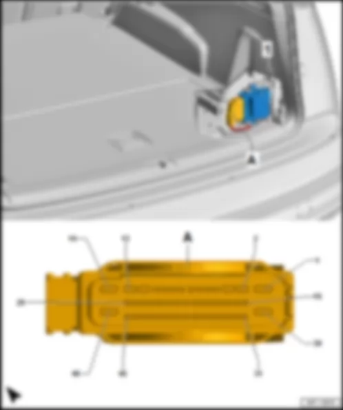
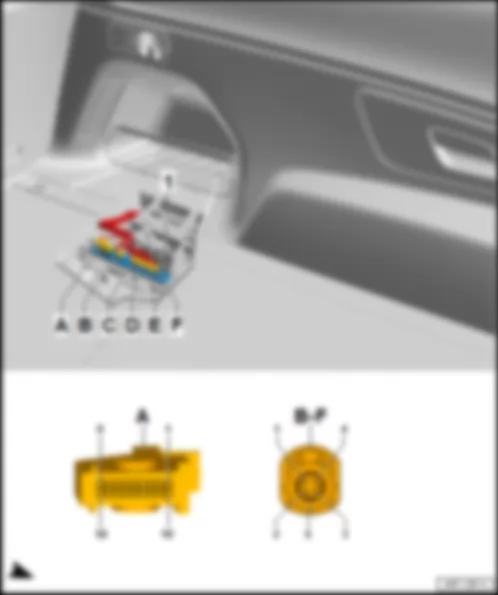
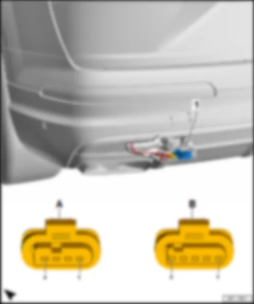
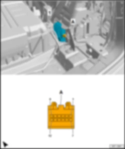
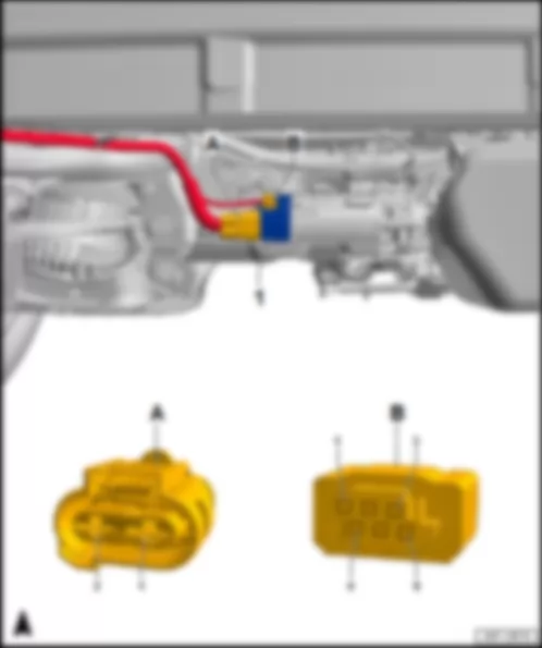
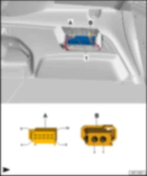
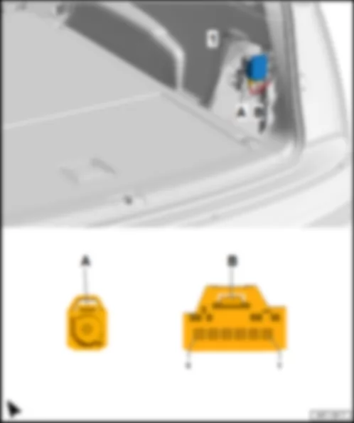
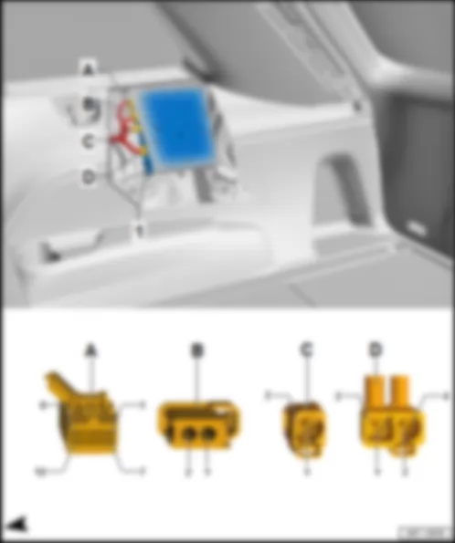
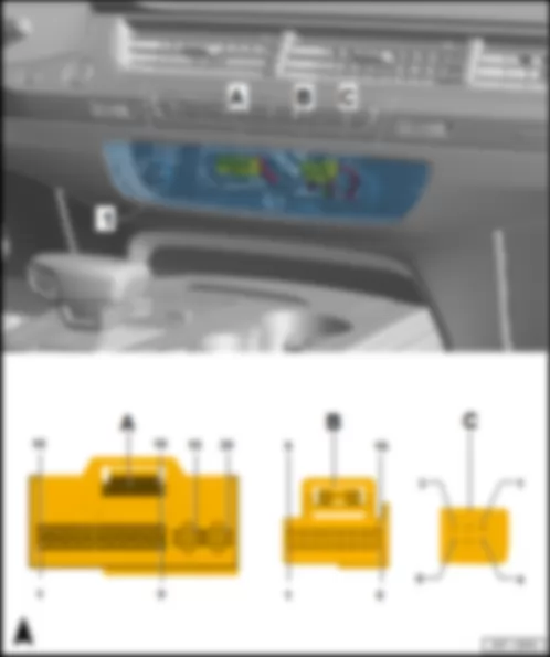
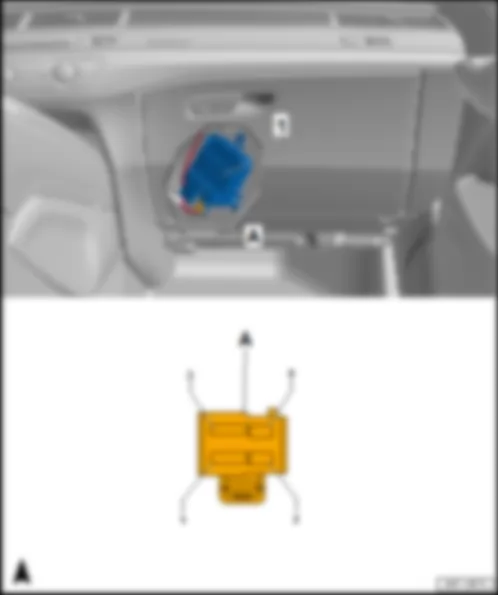
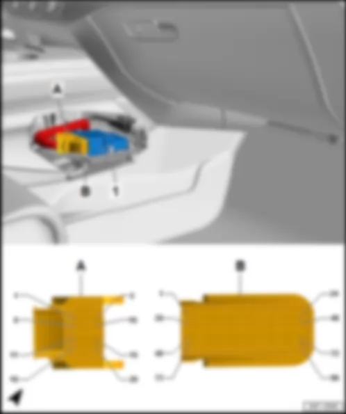
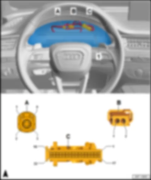
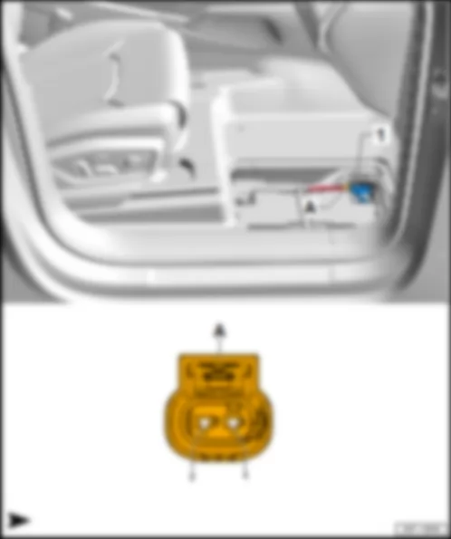
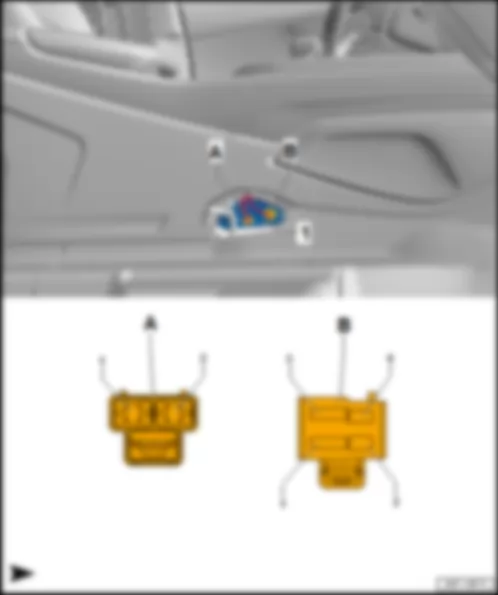
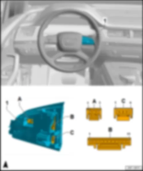
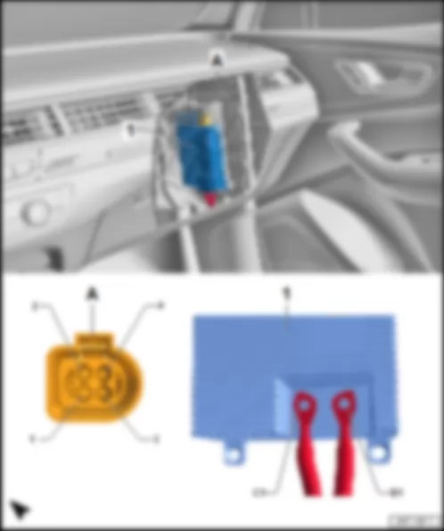
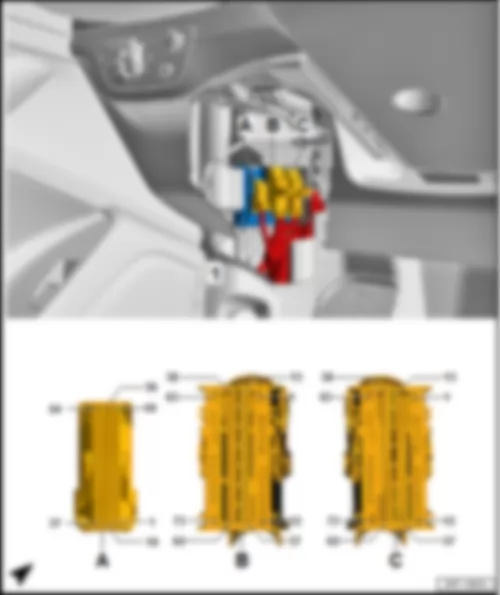
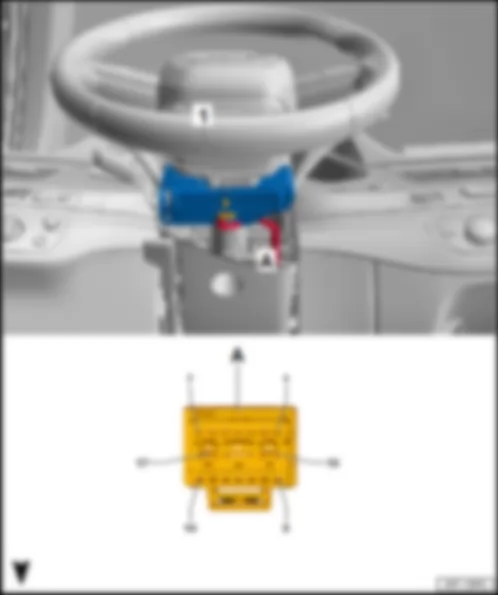
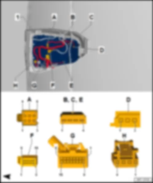
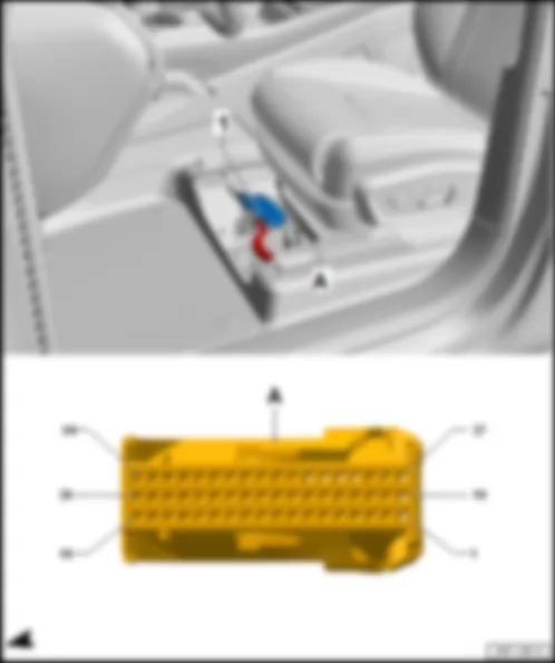
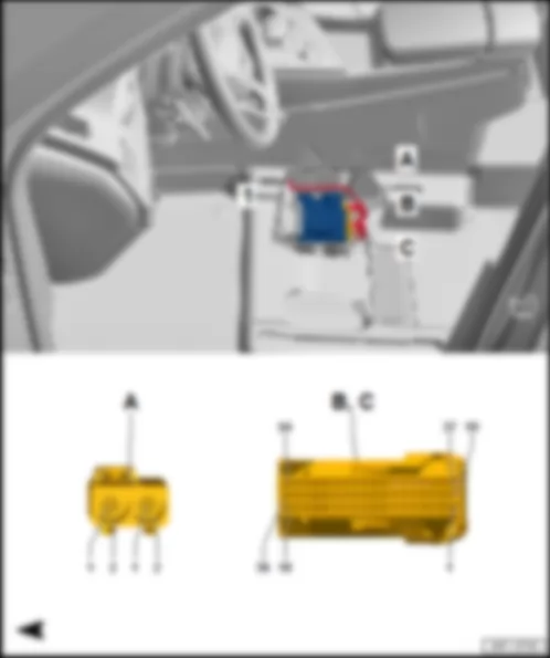
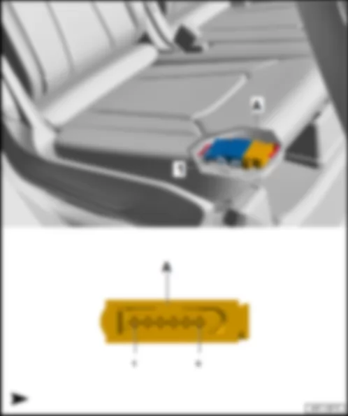
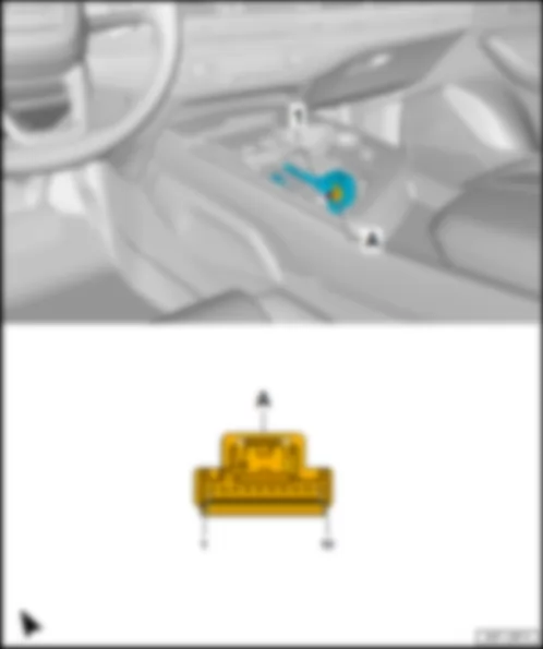
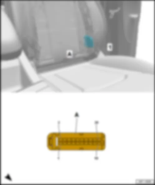
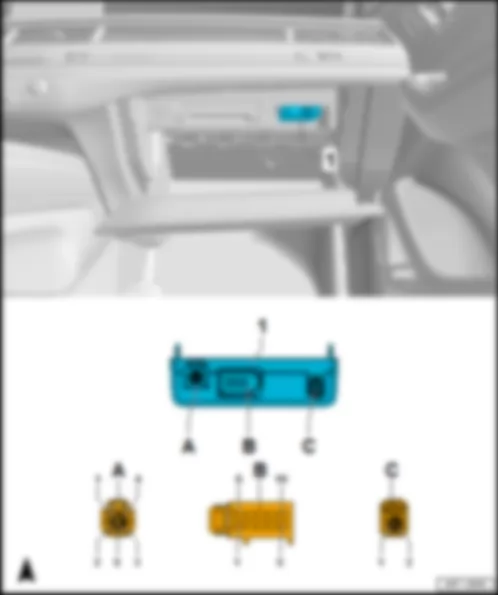
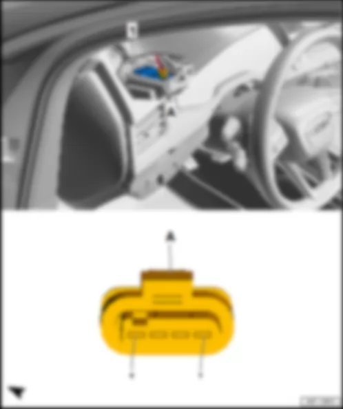
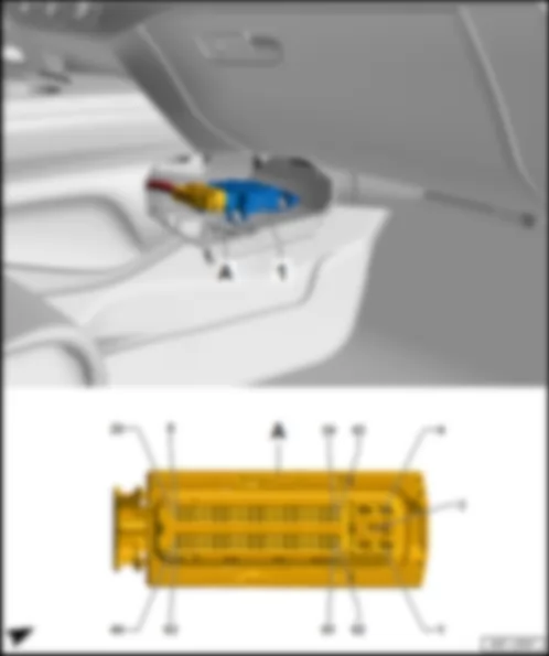
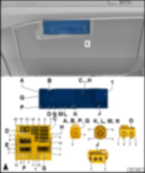
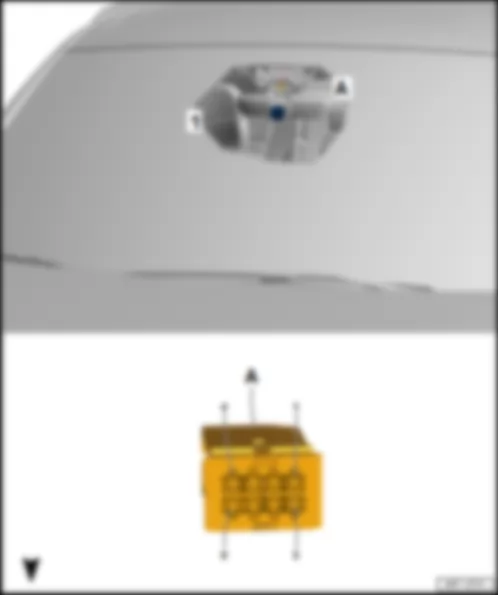
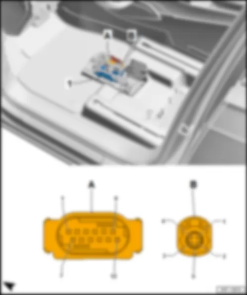
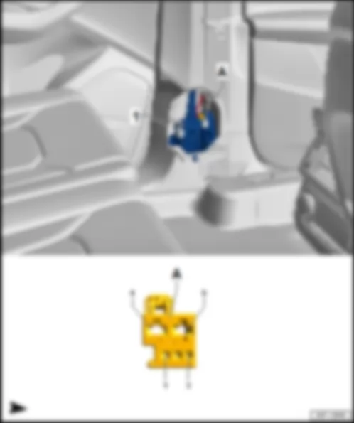
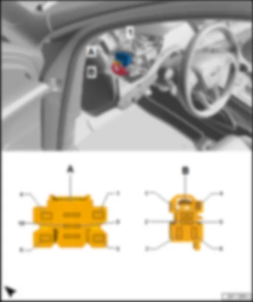
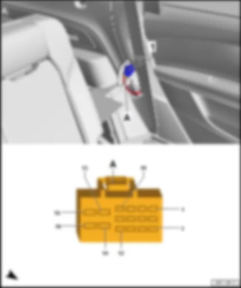
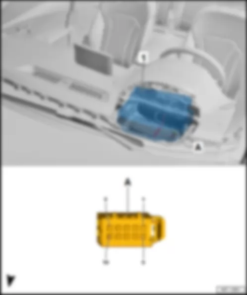
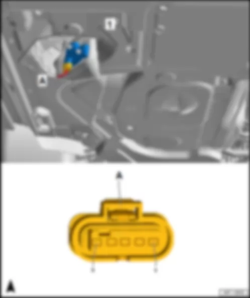
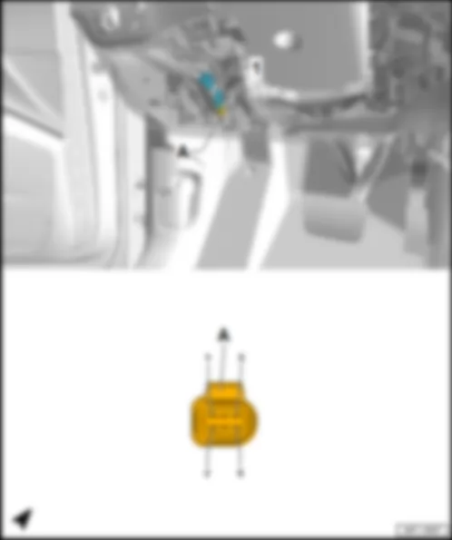
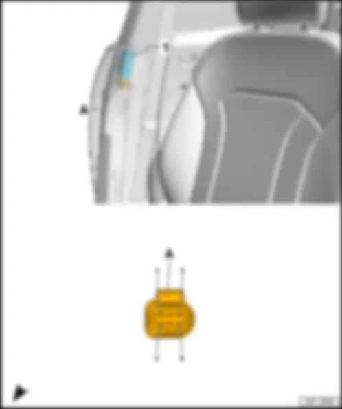
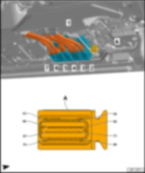
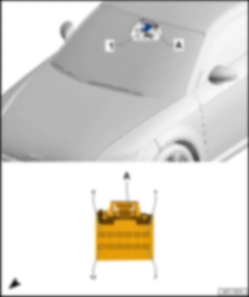
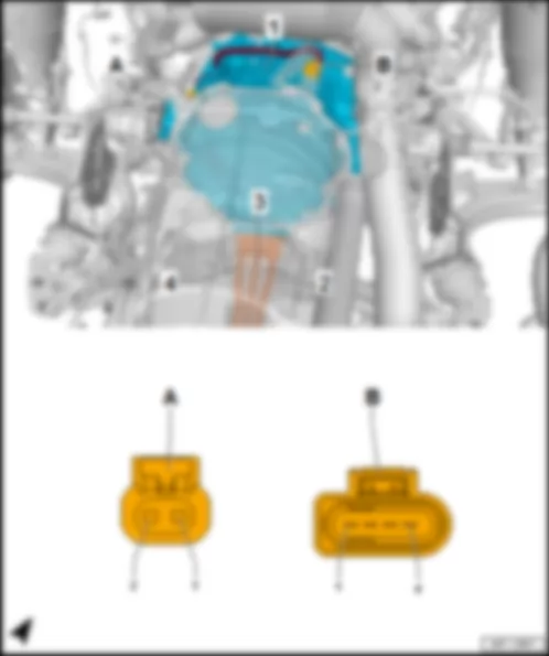
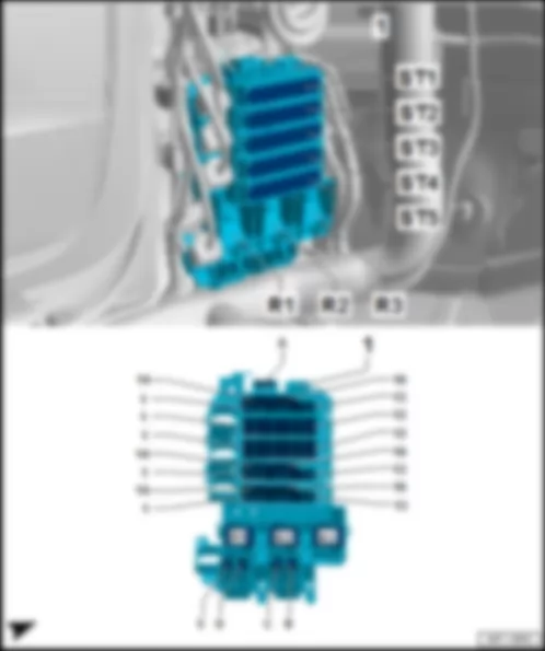
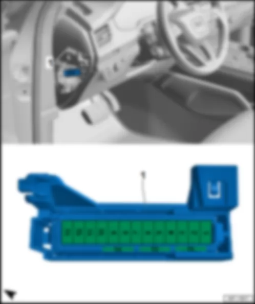
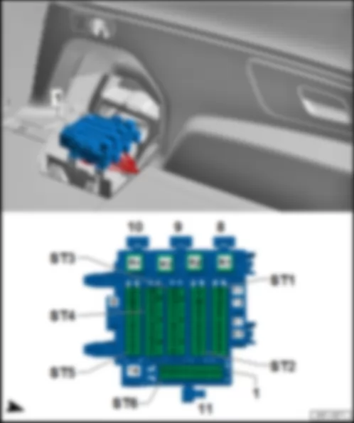
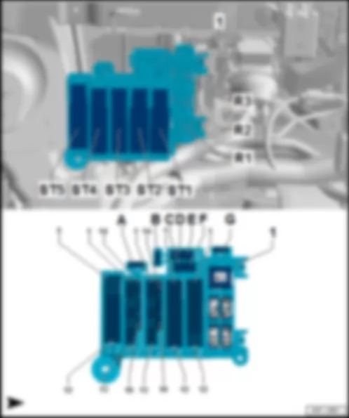
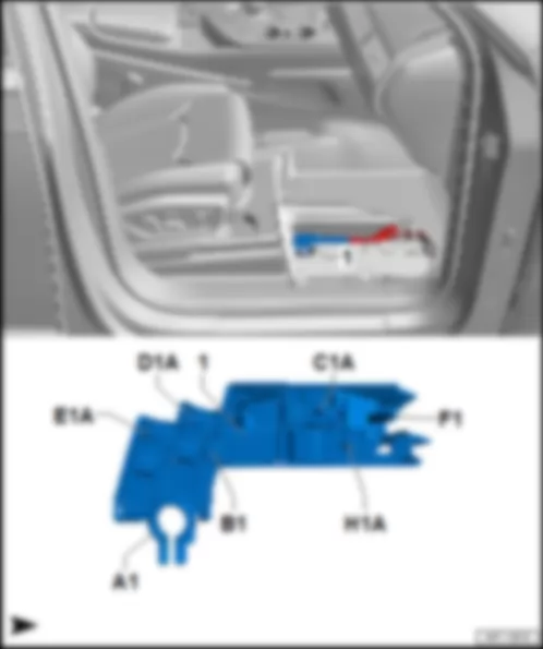
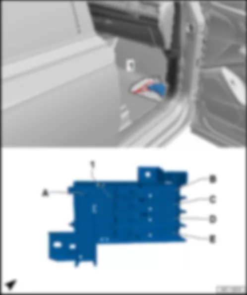
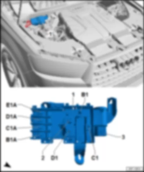
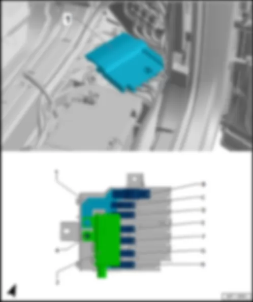
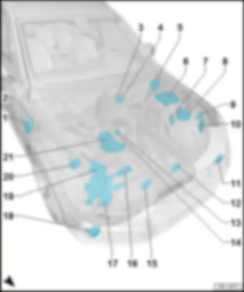
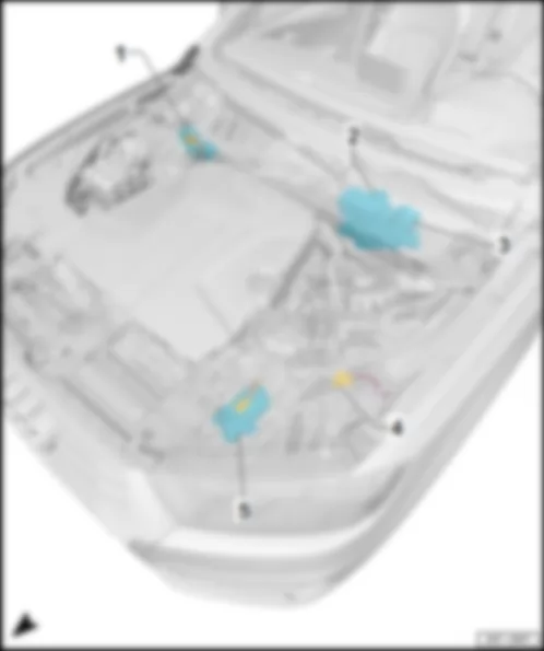
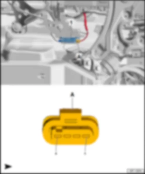
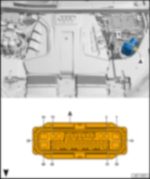
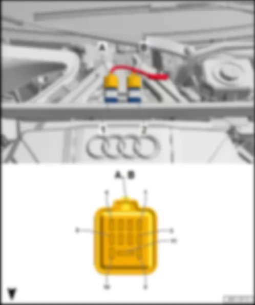
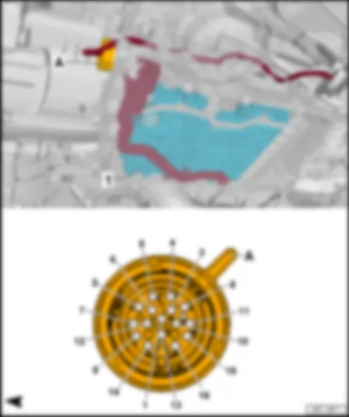
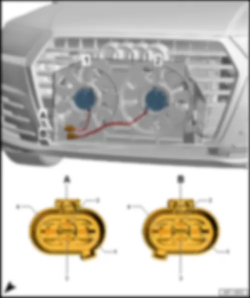
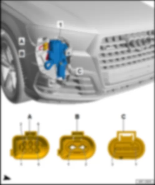
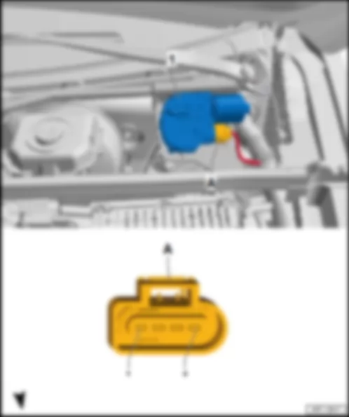
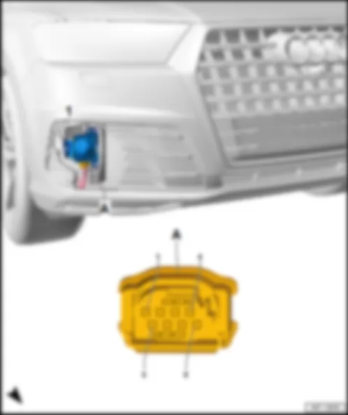
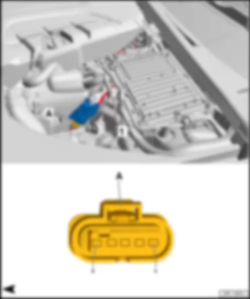
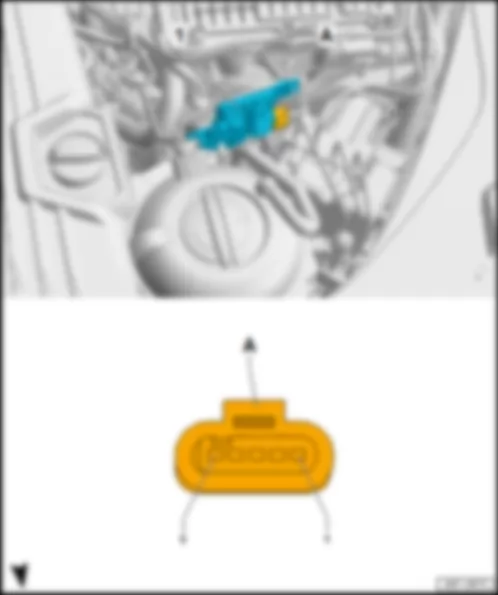
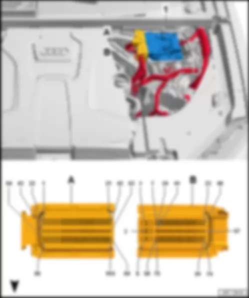
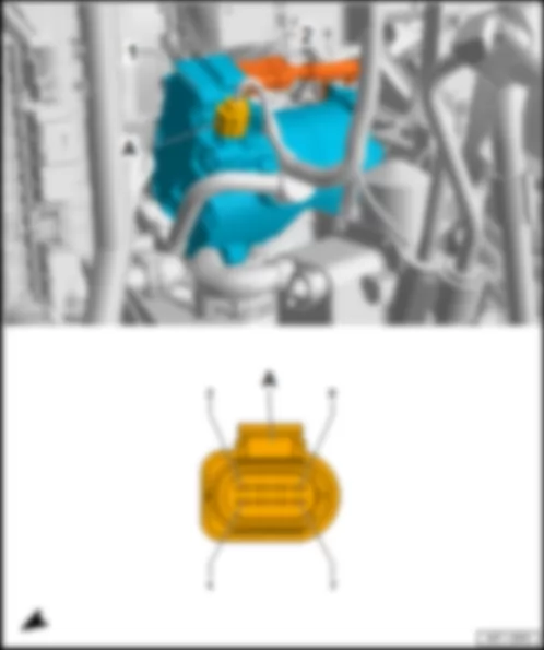
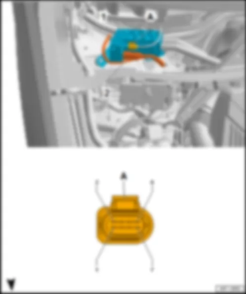
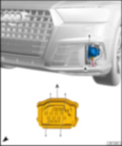
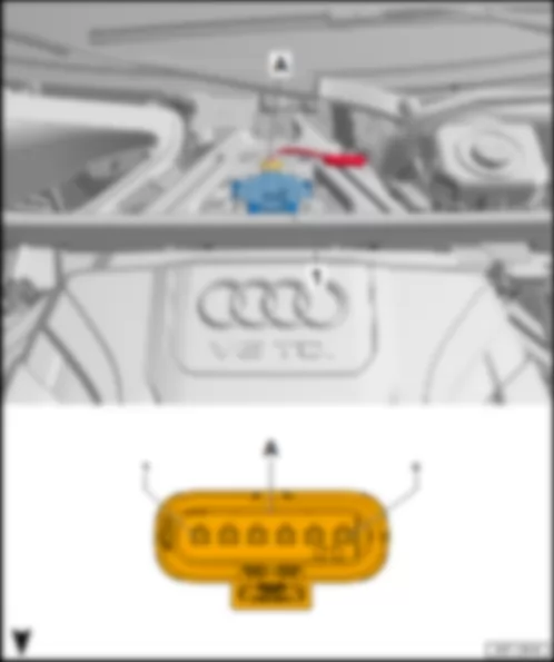
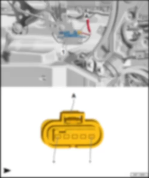
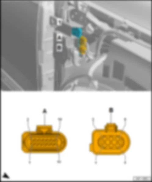
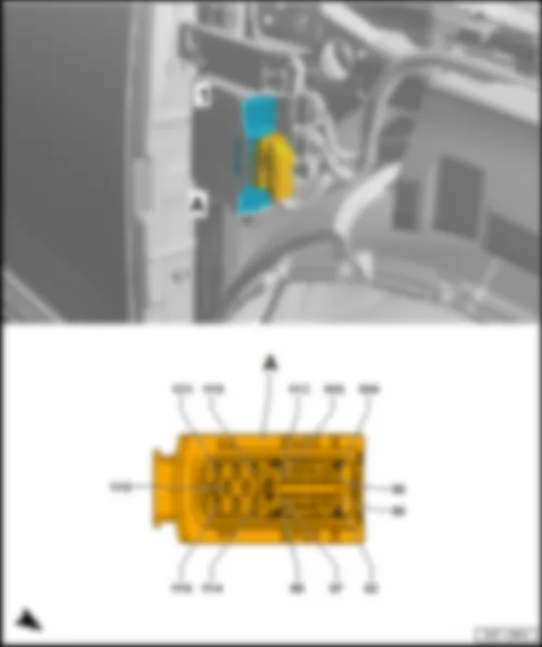
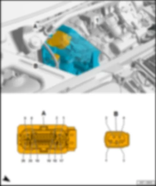
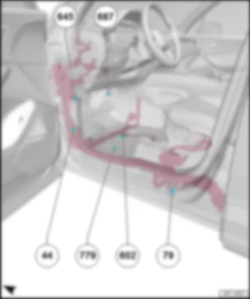
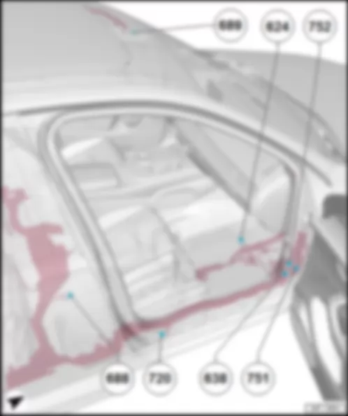
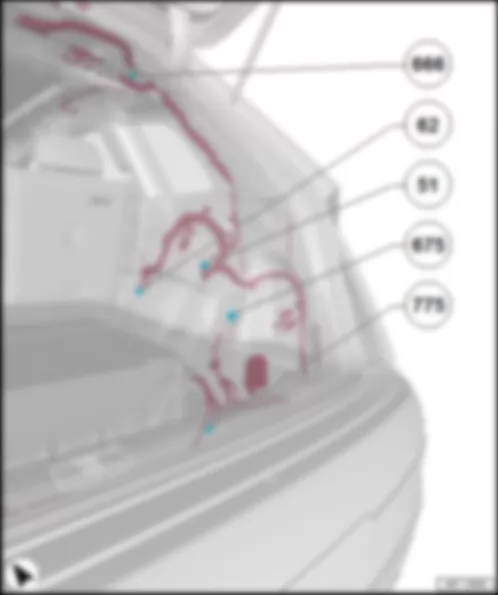
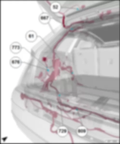
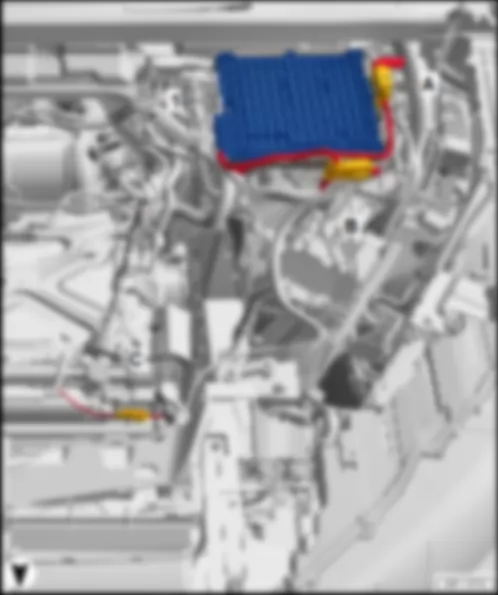
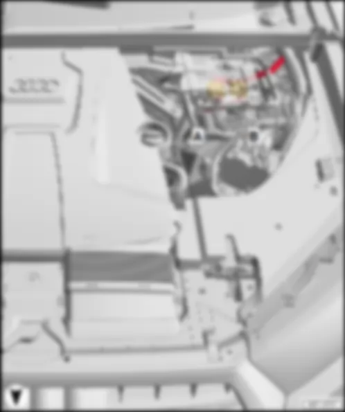
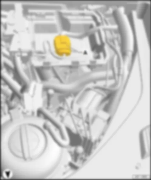
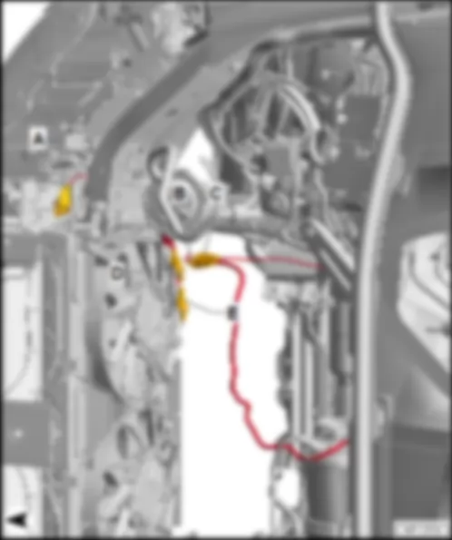
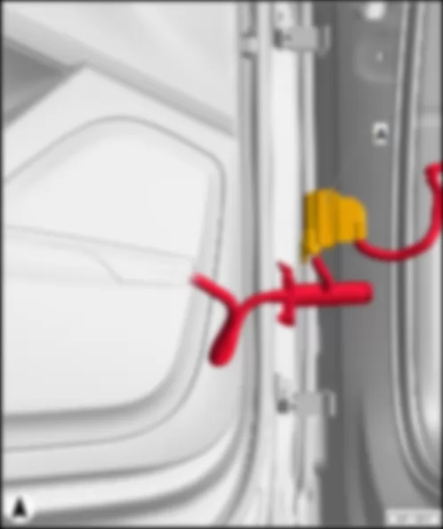
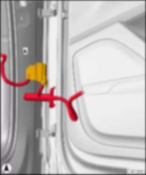
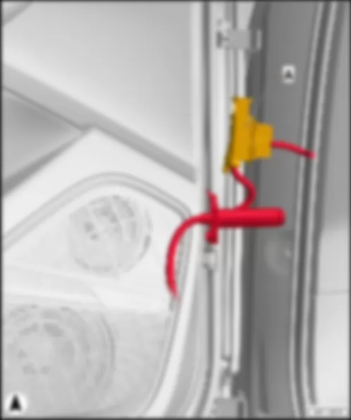
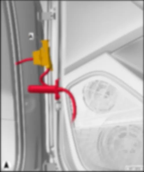
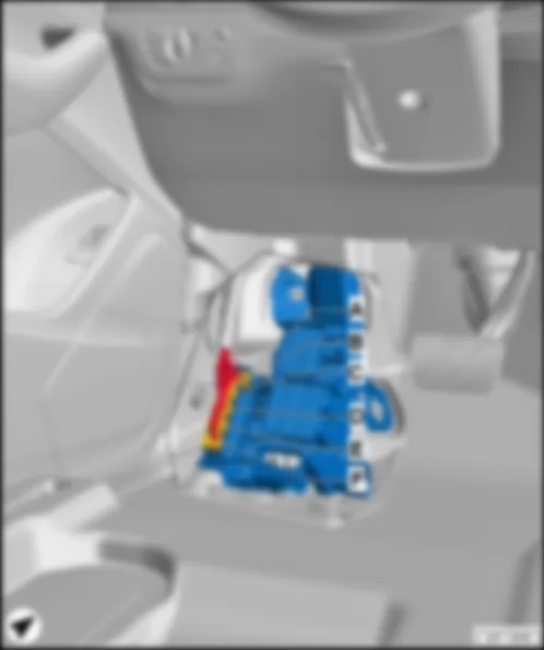
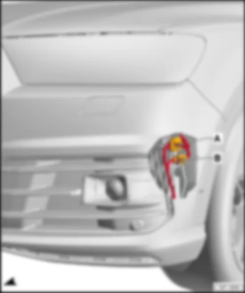
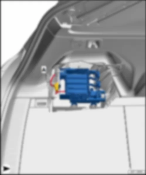
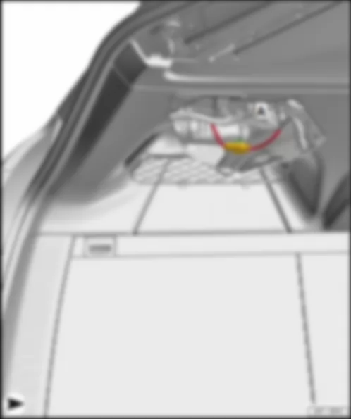
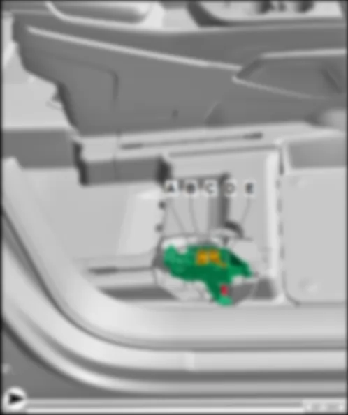
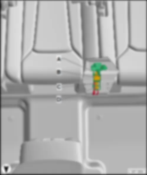
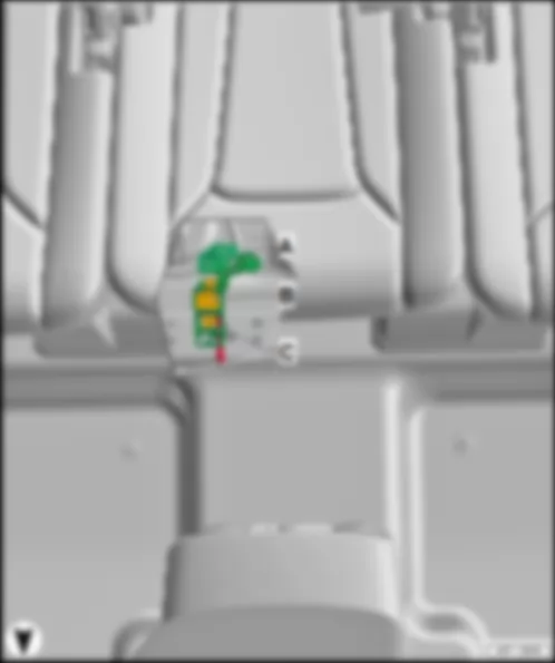
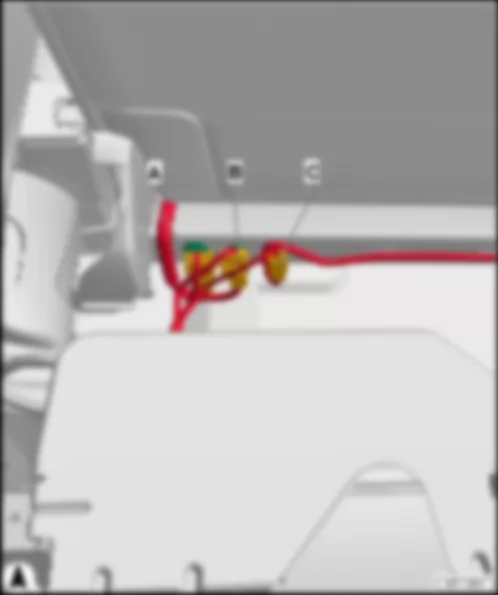
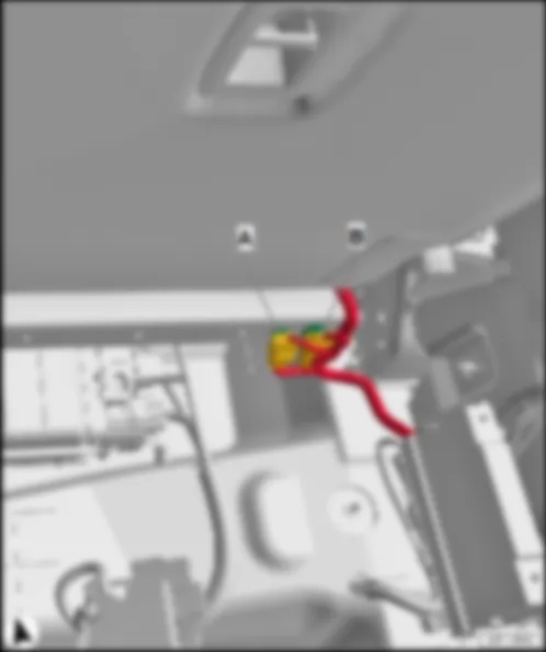
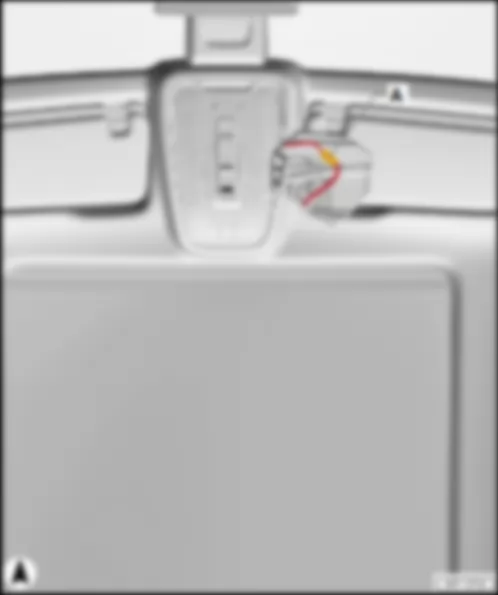
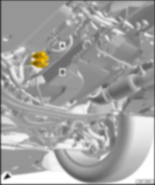
| -T20d- (A) | Designation | | -T16k- (B) | Designation |
| 1 | | | 1 | Rear temperature flap control motor -V137- |
| 2 | Drive high CAN bus, from coupling point at bottom on left A-pillar -TALU-
B385 Connection 3 (powertrain CAN bus, high), in main wiring harness
B384 Connection 2 (powertrain CAN bus, high), in main wiring harness
Data bus diagnostic interface -J533- | | 2 | Terminal 30, to L5 connection 1 in air conditioner unit wiring harness
Defroster flap control motor -V107-
Rear temperature flap control motor -V137-
Left temperature flap control motor -V158-
Left side vent control motor -V299-
Right side vent control motor -V300-
L6 Connection 2 in air conditioning system wiring harness
Air recirculation flap control motor -V113-
Right temperature flap control motor -V159-
Rear air distribution flap control motor -V427-
Fresh air flap control motor -V438-
Auxiliary air heater control unit -J604- |
| 3 | Drive low CAN bus, from coupling point at bottom on left A-pillar -TALU-
B392 Connection 3 (powertrain CAN bus, low), in main wiring harness
B391 Connection 2 (powertrain CAN bus, low), in main wiring harness
Data bus diagnostic interface -J533- | | 3 | Earth, to 112 earth connection 2 in air conditioning system wiring harness
Defroster flap control motor -V107-
Air recirculation flap control motor -V113-
Rear temperature flap control motor -V137-
Left temperature flap control motor -V158-
Right temperature flap control motor -V159-
Left side vent control motor -V299-
Right side vent control motor -V300-
Rear air distribution flap control motor -V427-
Fresh air flap control motor -V438- |
| 4 | LIN bus, to A227 connection 2 (LIN bus) in dash panel wiring harness
Fresh air blower control unit -J126-
Coupling point on left A-pillar, bottom -TALU-
B698 Connection 3 (LIN bus) in main wiring harness
High-pressure sender -G65-
Humidity sender in fresh air intake duct -G657- , air quality sensor -G238- | | 4 | Evaporator output temperature sender -G263- |
| 5 | | | 5 | Left footwell vent temperature sender -G261- |
| 6 | Photosensor for sunlight intensity -G107- | | 6 | Right footwell vent temperature sender -G262- |
| 7 | Earth, to 335 earth connection 5 in dash panel wiring harness
Photosensor for sunlight intensity -G107-
Front left chest vent temperature sensor -G385-
Front right chest vent temperature sensor -G386-
Coupling point on left A-pillar, bottom -TALU-
Rear chest vent temperature sensor -G537- | | 7 | |
| 8 | Photosensor for sunlight intensity -G107- | | 8 | |
| 9 | Photosensor for sunlight intensity -G107- | | 9 | Earth, to 97 earth connection 1 in air conditioning system wiring harness
Left footwell vent temperature sender -G261-
Right footwell vent temperature sender -G262-
Evaporator output temperature sender -G263- |
| 10 | | | 10 | |
| 11 | Front left chest vent temperature sensor -G385- | | 11 | Auxiliary air heater control unit -J604- |
| 12 | Front right chest vent temperature sensor -G386- | | 12 | |
| 13 | | | 13 | |
| 14 | | | 14 | |
| 15 | Rear chest vent temperature sensor -G537- | | 15 | |
| 16 | Terminal 30, to coupling point at bottom on left A-pillar -TALU-
B487 connection 23 in main wiring harness
High-pressure sender -G65-
Humidity sender in fresh air intake duct -G657- , air quality sensor -G238- | | 16 | |
| 17 | | | | |
| 18 | | | | |
| 19 | Terminal 31, to 752 earth point 3 on right A-pillar1)
687 Earth point 1 on centre tunnel2) | | | |
| 20 | Terminal 30, from fuse holder C -SC- | | | |
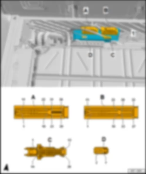
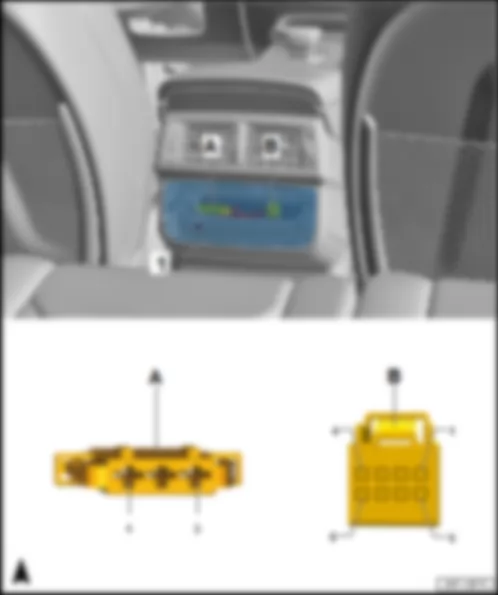
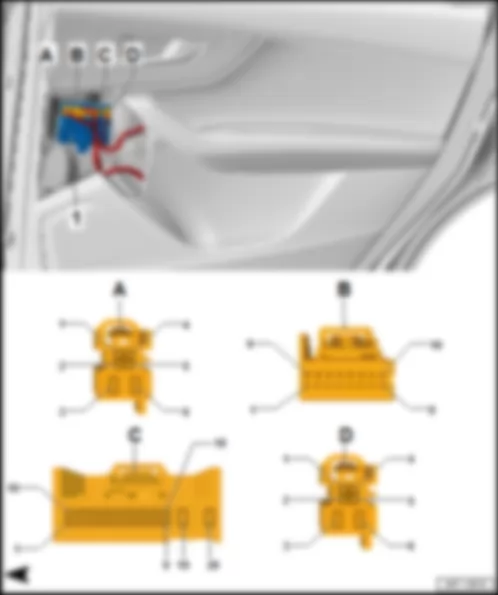
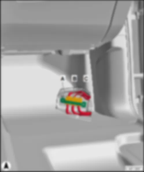
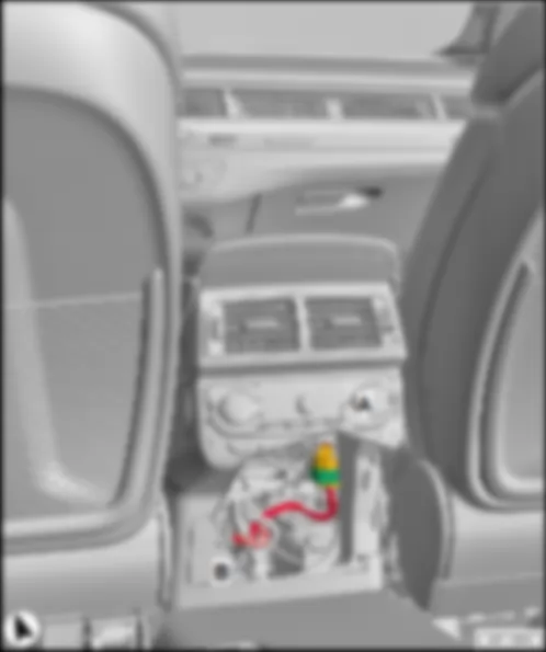
| -T20d- (A) | Designation | | -T16k- (B) | Designation |
| 1 | | | 1 | Rear temperature flap control motor -V137- |
| 2 | Drive high CAN bus, from coupling point at bottom on left A-pillar -TALU-
B385 Connection 3 (powertrain CAN bus, high), in main wiring harness
B384 Connection 2 (powertrain CAN bus, high), in main wiring harness
Data bus diagnostic interface -J533- | | 2 | Terminal 30, to L5 connection 1 in air conditioner unit wiring harness
Defroster flap control motor -V107-
Rear temperature flap control motor -V137-
Left temperature flap control motor -V158-
Left side vent control motor -V299-
Right side vent control motor -V300-
L6 Connection 2 in air conditioning system wiring harness
Air recirculation flap control motor -V113-
Right temperature flap control motor -V159-
Rear air distribution flap control motor -V427-
Fresh air flap control motor -V438-
Auxiliary air heater control unit -J604- |
| 3 | Drive low CAN bus, from coupling point at bottom on left A-pillar -TALU-
B392 Connection 3 (powertrain CAN bus, low), in main wiring harness
B391 Connection 2 (powertrain CAN bus, low), in main wiring harness
Data bus diagnostic interface -J533- | | 3 | Earth, to 112 earth connection 2 in air conditioning system wiring harness
Defroster flap control motor -V107-
Air recirculation flap control motor -V113-
Rear temperature flap control motor -V137-
Left temperature flap control motor -V158-
Right temperature flap control motor -V159-
Left side vent control motor -V299-
Right side vent control motor -V300-
Rear air distribution flap control motor -V427-
Fresh air flap control motor -V438- |
| 4 | LIN bus, to A227 connection 2 (LIN bus) in dash panel wiring harness
Fresh air blower control unit -J126-
Coupling point on left A-pillar, bottom -TALU-
B698 Connection 3 (LIN bus) in main wiring harness
Rear Climatronic operating and display unit -E265-
High-pressure sender -G65-
Humidity sender in fresh air intake duct -G657- , air quality sensor -G238-
Coupling point in interior, centre -TIM-
Rear fresh air blower control unit -J391-
Rear right chest vent control motor -V316- | | 4 | Evaporator output temperature sender -G263- |
| 5 | | | 5 | Left footwell vent temperature sender -G261- |
| 6 | Photosensor for sunlight intensity -G107- | | 6 | Right footwell vent temperature sender -G262- |
| 7 | Earth, to 335 earth connection 5 in dash panel wiring harness
Photosensor for sunlight intensity -G107-
Front left chest vent temperature sensor -G385-
Front right chest vent temperature sensor -G386- | | 7 | |
| 8 | Photosensor for sunlight intensity -G107- | | 8 | |
| 9 | Photosensor for sunlight intensity -G107- | | 9 | Earth, to 97 earth connection 1 in air conditioning system wiring harness
Left footwell vent temperature sender -G261-
Right footwell vent temperature sender -G262-
Evaporator output temperature sender -G263- |
| 10 | | | 10 | |
| 11 | Front left chest vent temperature sensor -G385- | | 11 | Auxiliary air heater control unit -J604- |
| 12 | Front right chest vent temperature sensor -G386- | | 12 | |
| 13 | | | 13 | |
| 14 | | | 14 | |
| 15 | | | 15 | |
| 16 | Terminal 30, to coupling point at bottom on left A-pillar -TALU-
B487 connection 23 in main wiring harness
High-pressure sender -G65-
Humidity sender in fresh air intake duct -G657- , air quality sensor -G238-
Coupling point in interior, centre -TIM-
L31 Connection (5 volt) in air conditioning unit wiring harness
Right B-pillar and footwell shut-off flap control motor -V211-
Left B-pillar and footwell shut-off flap control motor -V212-
Rear left chest vent control motor -V315-
Rear right chest vent control motor -V316- | | 16 | |
| 17 | Earth, to coupling point on right A-pillar, bottom -TARU-
Coupling point in interior, centre -TIM-
188 Earth connection 3 in air conditioning system wiring harness
Right B-pillar and footwell shut-off flap control motor -V211-
Left B-pillar and footwell shut-off flap control motor -V212-
Rear left chest vent control motor -V315-
Rear right chest vent control motor -V316- | | | |
| 18 | | | | |
| 19 | Terminal 31, to 752 earth point 3 on right A-pillar1)
687 Earth point 1 on centre tunnel2) | | | |
| 20 | Terminal 30, from fuse holder C -SC- | | | |
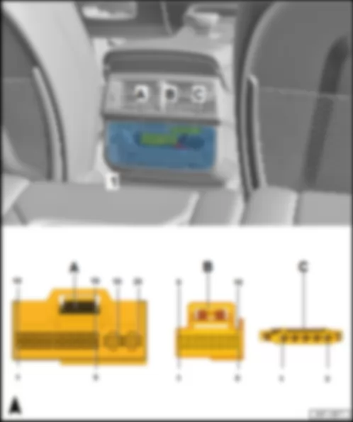
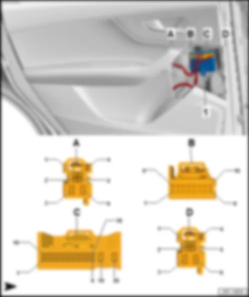
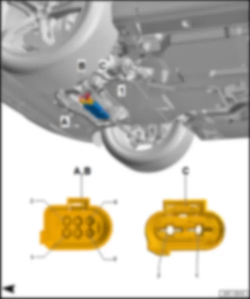
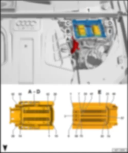
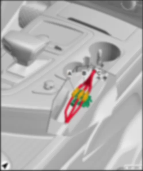
| -T20d- (A) | Designation | | -T16k- (B) | Designation | | -T6g- (C) | Designation |
| 1 | | | 1 | Left footwell flap control motor -V108- | | 1 | Potentiometer in rear right chest vent -G631- |
| 2 | Drive high CAN bus, from coupling point at bottom on left A-pillar -TALU-
B385 Connection 3 (powertrain CAN bus, high), in main wiring harness
B384 Connection 2 (powertrain CAN bus, high), in main wiring harness
Data bus diagnostic interface -J533- | | 2 | Terminal 30, to L5 connection 1 in air conditioner unit wiring harness
Defroster flap control motor -V107-
Left footwell flap control motor -V108-
Left centre vent control motor -V110-
Rear temperature flap control motor -V137-
Left temperature flap control motor -V158-
Left side vent control motor -V299-
Control motor for left footwell temperature flap -V411-
L6 Connection 2 in air conditioning system wiring harness
Right footwell flap control motor -V109-
Right central vent control motor -V111-
Air recirculation flap control motor -V113-
Right temperature flap control motor -V159-
Right side vent control motor -V300-
Right footwell temperature flap control motor -V412-
Rear air distribution flap control motor -V427-
Fresh air flap control motor -V438- | | 2 | Potentiometer in rear left chest vent -G630- |
| 3 | Drive low CAN bus, from coupling point at bottom on left A-pillar -TALU-
B392 Connection 3 (powertrain CAN bus, low), in main wiring harness
B391 Connection 2 (powertrain CAN bus, low), in main wiring harness
Data bus diagnostic interface -J533- | | 3 | Earth, to 112 earth connection 2 in air conditioning system wiring harness
Defroster flap control motor -V107-
Left footwell flap control motor -V108-
Left centre vent control motor -V110-
Rear temperature flap control motor -V137-
Left temperature flap control motor -V158-
Left side vent control motor -V299-
Control motor for left footwell temperature flap -V411-
188 Earth connection 3 in air conditioning system wiring harness
Right footwell flap control motor -V109-
Right central vent control motor -V111-
Air recirculation flap control motor -V113-
Right temperature flap control motor -V159-
Right side vent control motor -V300-
Right footwell temperature flap control motor -V412-
Rear air distribution flap control motor -V427-
Fresh air flap control motor -V438- | | 3 | Potentiometer in left side vent -G628- |
| 4 | LIN bus, to A227 connection 2 (LIN bus) in dash panel wiring harness
Fresh air blower control unit -J126-
Driver-side ioniser -J1105-
Dash panel vent control motor -V562-
Coupling point on left A-pillar, bottom -TALU-
B698 Connection 3 (LIN bus) in main wiring harness
High-pressure sender -G65-
Humidity sender in fresh air intake duct -G657- , air quality sensor -G238-
Coupling point in interior, centre -TIM-
Rear fresh air blower control unit -J391- | | 4 | Evaporator output temperature sender -G263- | | 4 | Potentiometer in right side vent -G629- |
| 5 | | | 5 | Left footwell vent temperature sender -G261- | | 5 | Potentiometer in left centre vent -G626- |
| 6 | 5V output, to A58 connection (5 Volt) in instrument panel wiring harness
Photosensor for sunlight intensity -G107-
Potentiometer in left centre vent -G626-
Potentiometer in right centre dash panel vent -G627-
Potentiometer in left side vent -G628-
Potentiometer in right side vent -G629-
Potentiometer in rear left chest vent -G630-
Potentiometer in rear right chest vent -G631- | | 6 | Right footwell vent temperature sender -G262- | | 6 | Potentiometer in right centre dash panel vent -G627- |
| 7 | Earth, to 335 earth connection 5 in dash panel wiring harness
Photosensor for sunlight intensity -G107-
Front left chest vent temperature sensor -G385-
Front right chest vent temperature sensor -G386-
822 Earth connection 8 in dash panel wiring harness
Dash panel vent button -E815-
Potentiometer in left centre vent -G626-
Potentiometer in right centre dash panel vent -G627-
Potentiometer in left side vent -G628-
Potentiometer in right side vent -G629-
Potentiometer in rear left chest vent -G630-
Potentiometer in rear right chest vent -G631-
| | 7 | | | | |
| 8 | Photosensor for sunlight intensity -G107- | | 8 | | | | |
| 9 | Photosensor for sunlight intensity -G107- | | 9 | Earth, to 97 earth connection 1 in air conditioning system wiring harness
Left footwell vent temperature sender -G261-
Right footwell vent temperature sender -G262-
Evaporator output temperature sender -G263- | | | |
| 10 | | | 10 | | | | |
| 11 | Front left chest vent temperature sensor -G385- | | 11 | Auxiliary air heater control unit -J604- | | | |
| 12 | Front right chest vent temperature sensor -G386- | | 12 | | | | |
| 13 | Dash panel vent button -E815- | | 13 | | | | |
| 14 | Dash panel vent button -E815- | | 14 | | | | |
| 15 | | | 15 | | | | |
| 16 | Terminal 30, to A68 connection (30, air conditioning system) in dash panel wiring harness
Driver-side ioniser -J1105-
Dash panel vent control motor -V562-
Coupling point on left A-pillar, bottom -TALU-
B487 connection 23 in main wiring harness
High-pressure sender -G65-
Humidity sender in fresh air intake duct -G657- , air quality sensor -G238- | | 16 | | | | |
| 17 | Dash panel vent control motor -V562- | | | | | | |
| 18 | | | | | | | |
| 19 | Terminal 31, to 752 earth point 3 on right A-pillar1)
687 Earth point 1 on centre tunnel2) | | | | | | |
| 20 | Terminal 30, from fuse holder C -SC- | | | | | | |
| -T20e- (A) | Designation | | -T16l- (B) | Designation | | -T5i- (C) | Designation |
| 1 | | | 1 | Rear right temperature flap control motor -V314- | | 1 | Heated bench seat cushion for rear left seat -Z10- |
| 2 | Drive high CAN bus from B384 connection 2 (drive high CAN bus) in main wiring harness
Data bus diagnostic interface -J533- | | 2 | Terminal 30, to L9 connection 1 in air conditioning system wiring harness
Left B-pillar and footwell shut-off flap control motor -V212-
Rear left temperature flap control motor -V313-
Rear left chest vent control motor -V315-
Rear air recirculation flap control motor -V421-
L31 Connection (5 volt) in air conditioning unit wiring harness
Right B-pillar and footwell shut-off flap control motor -V211-
Rear right temperature flap control motor -V314-
Rear right chest vent control motor -V316- | | 2 | heated backrest for rear left seat -Z11- |
| 3 | Drive low CAN bus, from B391 connection 2 (drive low CAN bus) in main wiring harness
Data bus diagnostic interface -J533- | | 3 | Earth, to L10 connection 2 in air conditioning system wiring harness
Left B-pillar and footwell shut-off flap control motor -V212-
Rear left temperature flap control motor -V313-
Rear left chest vent control motor -V315-
Rear air recirculation flap control motor -V421-
L2 Connection in air conditioning system wiring harness
Right B-pillar and footwell shut-off flap control motor -V211-
Rear right temperature flap control motor -V314-
Rear right chest vent control motor -V316- | | 3 | Terminal 30, from fuse carrier 1 -ST1- in fuse holder F -SF- |
| 4 | Rear passenger side ioniser -J1108- | | 4 | Rear left chest vent temperature sender -G635- | | 4 | Heated bench seat cushion for rear right seat -Z12- |
| 5 | | | 5 | Vent temperature sender for rear left footwell -G637- | | 5 | Heated backrest for rear right seat -Z13- |
| 6 | | | 6 | Vent temperature sender for rear right footwell -G638- | | | |
| 7 | Earth, torear left seat temperature sensor -G94- /rear right seat temperature sensor -G95- /rear left backrest temperature sensor -G808- /rear right backrest temperature sensor -G809- | | 7 | | | | |
| 8 | | | 8 | | | | |
| 9 | | | 9 | Rear right chest vent temperature sender -G636- | | | |
| 10 | | | 10 | Earth, to L7 connection 3 in air conditioner unit wiring harness
Rear left chest vent temperature sender -G635-
Rear right chest vent temperature sender -G636-
Vent temperature sender for rear left footwell -G637-
Vent temperature sender for rear right footwell -G638- | | | |
| 11 | | | 11 | | | | |
| 12 | | | 12 | | | | |
| 13 | | | 13 | | | | |
| 14 | | | 14 | | | | |
| 15 | Rear left seat temperature sensor -G94- | | 15 | | | | |
| 16 | Rear left seat backrest temperature sensor -G808- | | 16 | | | | |
| 17 | Rear right seat temperature sensor -G95- | | | | | | |
| 18 | Rear right seat backrest temperature sensor -G809- | | | | | | |
| 19 | Terminal 31, to 398 earth connection 33 in main wiring harness
393 Earth connection 28 in main wiring harness
688 Earth point 2 on centre tunnel | | | | | | |
| 20 | Terminal 30, from fuse carrier 2 -ST2- in fuse holder F -SF- | | | | | | |
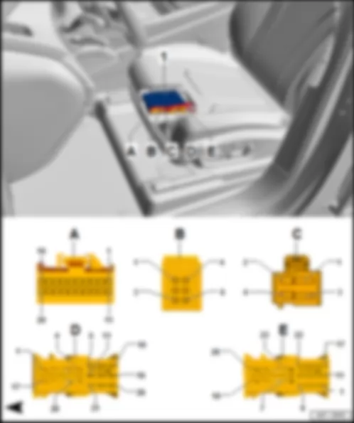
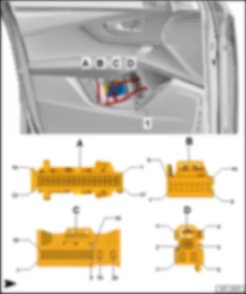
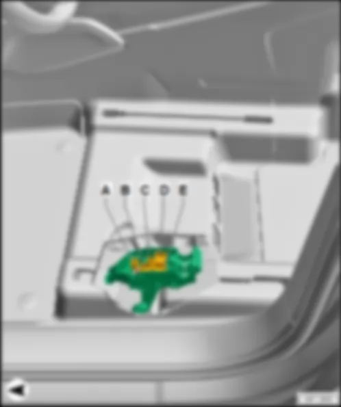
| -T26f- (D) | Designation | | -T26b- (E) | Designation |
| 1 | Backrest adjustment sender for driver seat -G219- /driver seat backrest adjustment motor -V45- | | 1 | |
| 2 | | | 2 | |
| 3 | Driver seat lumbar support longitudinal adjustment motor -V125-1) /driver seat lumbar support height adjustment motor -V596-2) | | 3 | Longitudinal adjustment sender for driver seat -G218- |
| 4 | | | 4 | Switch module for driver seat -E663-1) |
| 5 | | | 5 | Earth, to switch module for driver seat -E663-1) /driver seat massage function button -E670-2) /longitudinal adjustment sender for driver seat -G218- |
| 6 | | | 6 | |
| 7 | Lumbar support height adjustment sender -G374-1) | | 7 | Rake adjustment sender for driver seat -G232- /driver seat rake adjustment motor -V243- |
| 8 | Lumbar support longitudinal adjustment sender -G375-1) | | 8 | Driver seat longitudinal adjustment motor -V28- |
| 9 | | | 9 | Seat depth adjustment sender -G378-1) /driver seat depth adjustment motor -V256-1) |
| 10 | | | 10 | Height adjustment sender for driver seat -G231- /driver seat height adjustment motor -V245- |
| 11 | | | 11 | |
| 12 | | | 12 | Driver seat massage function button -E670-2) |
| 13 | | | 13 | |
| 14 | | | 14 | Switch module for driver seat -E663-1) |
| 15 | | | 15 | |
| 16 | Driver seat lumbar support height adjustment motor -V129-1) | | 16 | |
| 17 | | | 17 | Switch module for driver seat -E663-1) |
| 18 | Driver seat lumbar support longitudinal adjustment motor -V125-1) /driver seat lumbar support height adjustment motor -V596-2) | | 18 | |
| 19 | Backrest adjustment sender for driver seat -G219- /driver seat backrest adjustment motor -V45- | | 19 | |
| 20 | | | 20 | |
| 21 | | | 21 | |
| 22 | Earth, to lumbar support height adjustment sender -G374-1) /lumbar support longitudinal adjustment sender -G375-1) | | 22 | |
| 23 | | | 23 | Rake adjustment sender for driver seat -G232- /driver seat rake adjustment motor -V243- |
| 24 | | | 24 | Driver seat longitudinal adjustment motor -V28- |
| 25 | | | 25 | Height adjustment sender for driver seat -G231- /driver seat height adjustment motor -V245- |
| 26 | Driver seat lumbar support height adjustment motor -V129-1) | | 26 | Seat depth adjustment sender -G378-1) /driver seat depth adjustment motor -V256-1) |
| -T26g- (D) | Designation | | -T26c- (E) | Designation |
| 1 | Backrest adjustment sender for front passenger seat -G279- /front passenger seat backrest adjustment motor -V46- | | 1 | |
| 2 | | | 2 | |
| 3 | Front passenger seat lumbar support longitudinal adjustment motor -V126-1) /front passenger seat lumbar support height adjustment motor -V597-2) | | 3 | Longitudinal adjustment sender for front passenger seat -G278- |
| 4 | | | 4 | Switch module for front passenger seat -E664-1) |
| 5 | | | 5 | Earth, to switch module for front passenger seat -E664-1) /front passenger seat massage function button -E671-2) /longitudinal adjustment sender for front passenger seat -G278- |
| 6 | | | 6 | |
| 7 | Front passenger lumbar support height adjustment sender -G721-1) | | 7 | Rake adjustment sender for front passenger seat -G359- /front passenger seat rake adjustment motor -V244- |
| 8 | Front passenger lumbar support longitudinal adjustment sender -G722-1) | | 8 | Front passenger seat longitudinal adjustment motor -V31- |
| 9 | | | 9 | Front passenger seat depth adjustment sender -G724-1) /front passenger seat depth adjustment motor -V257-1) |
| 10 | | | 10 | Sender for height adjustment of front passenger seat -G607- /front passenger seat height adjustment motor -V246- |
| 11 | | | 11 | |
| 12 | | | 12 | Front passenger seat massage function button -E671-2) |
| 13 | | | 13 | |
| 14 | | | 14 | Switch module for front passenger seat -E664-1) |
| 15 | | | 15 | |
| 16 | Front passenger seat lumbar support height adjustment motor -V130-1) | | 16 | |
| 17 | | | 17 | Switch module for front passenger seat -E664-1) |
| 18 | Front passenger seat lumbar support longitudinal adjustment motor -V126-1) /front passenger seat lumbar support height adjustment motor -V597-2) | | 18 | |
| 19 | Backrest adjustment sender for front passenger seat -G279- /front passenger seat backrest adjustment motor -V46- | | 19 | |
| 20 | | | 20 | |
| 21 | | | 21 | |
| 22 | Earth, to front passenger lumbar support height adjustment sender -G721-1) /front passenger lumbar support longitudinal adjustment sender -G722-1) | | 22 | |
| 23 | | | 23 | Rake adjustment sender for front passenger seat -G359- /front passenger seat rake adjustment motor -V244- |
| 24 | | | 24 | Front passenger seat longitudinal adjustment motor -V31- |
| 25 | | | 25 | Sender for height adjustment of front passenger seat -G607- /front passenger seat height adjustment motor -V246- |
| 26 | Front passenger seat lumbar support height adjustment motor -V130-1) | | 26 | Front passenger seat depth adjustment sender -G724-1) /front passenger seat depth adjustment motor -V257-1) |
| -T32c- (A) | Designation | | -T16e- (B) | Designation |
| 1 | Central locking SAFELOCK function warning lamp -K133- | | 1 | |
| 2 | | | 2 | Driver side automatic anti-dazzle exterior mirror -Y20- |
| 3 | Light for driver side interior door handle illumination -L219- | | 3 | Driver side turn signal repeater bulb -L131- /heated exterior mirror on driver side -Z4- |
| 4 | Terminal 58s, to R52 connection (58s) in driver door wiring harness
Mirror adjustment switch -E43- /mirror adjustment changeover switch -E48-
Rear lid remote release button -E233-
Driver side interior locking button for central locking system -E308-
Driver side operating unit for memory settings -E464-
Operating unit for window regulator in driver door -E512-
Button for deactivating interior monitoring and vehicle inclination sensor -E616- | | 4 | Earth, to 107 earth connection in exterior mirror wiring harness
Potentiometer for horizontal adjustment of driver side mirror -G514- /potentiometer for vertical adjustment of driver side mirror -G515-
Lane change assist warning lamp in driver side exterior mirror -K233- |
| 5 | Earth, to 267 earth connection 2 in driver door wiring harness
Mirror adjustment switch -E43- /mirror adjustment changeover switch -E48-
Driver side interior locking button for central locking system -E308-
Driver side operating unit for memory settings -E464-
Operating unit for window regulator in driver door -E512-
Button for deactivating interior monitoring and vehicle inclination sensor -E616-
Central locking SAFELOCK function warning lamp -K133-
Light for driver side interior door handle illumination -L219-
Light for driver door ambient lighting -W86-
Light 2 for driver door ambient lighting -W97-
Driver door exit warning light -W111-
404 earth connection 4 in driver door wiring harness
Rear lid remote release button -E233-
Light for driver door loudspeaker trim -L223-
Driver side door warning lamp -W30-
Driver side entry light -W92- | | 5 | Driver side mirror adjustment motor -V17- /driver side mirror adjustment motor -V149- |
| 6 | Driver door exit warning light -W111- | | 6 | Driver side automatic anti-dazzle exterior mirror -Y20- |
| 7 | | | 7 | Driver side mirror adjustment motor -V17- |
| 8 | to R97 connection 4 in driver door wiring harness
Light for driver door loudspeaker trim -L223-
Light for driver door ambient lighting -W86-
Light 2 for driver door ambient lighting -W97- | | 8 | Driver side mirror adjustment motor -V149- |
| 9 | | | 9 | Driver side fold-in mirror motor -V121- |
| 10 | Button for deactivating interior monitoring and vehicle inclination sensor -E616- | | 10 | Driver side fold-in mirror motor -V121- |
| 11 | Operating unit for window regulator in driver door -E512-
Warning lamp for activated right childproof lock -K272- | | 11 | Driver side turn signal repeater bulb -L131- |
| 12 | Operating unit for window regulator in driver door -E512-
Warning lamp for activated left childproof lock -K271- | | 12 | Lane change assist warning lamp in driver side exterior mirror -K233- |
| 13 | Driver side interior locking button for central locking system -E308- | | 13 | Potentiometer for horizontal adjustment of driver side mirror -G514- |
| 14 | | | 14 | Potentiometer for horizontal adjustment of driver side mirror -G514- /potentiometer for vertical adjustment of driver side mirror -G515- |
| 15 | Driver side operating unit for memory settings -E464-
Driver seat memory function button -E283- | | 15 | Heated exterior mirror on driver side -Z4- |
| 16 | to R56 connection (entry light) in driver door wiring harness
Driver side door warning lamp -W30-
Driver side entry light -W92- | | 16 | Potentiometer for vertical adjustment of driver side mirror -G515- |
| 17 | Driver side operating unit for memory settings -E464- | | | |
| 18 | | | | |
| 19 | Driver side operating unit for memory settings -E464-
Seat memory position button 1 in driver door -E218- /seat memory position button 2 in driver door -E219- | | | |
| 20 | Button for deactivating interior monitoring and vehicle inclination sensor -E616- | | | |
| 21 | | | | |
| 22 | | | | |
| 23 | Rear lid remote release button -E233- | | | |
| 24 | Mirror adjustment switch -E43- | | | |
| 25 | Mirror adjustment changeover switch -E48- | | | |
| 26 | | | | |
| 27 | Operating unit for window regulator in driver door -E512- | | | |
| 28 | Driver side interior locking button for central locking system -E308- | | | |
| 29 | Operating unit for window regulator in driver door -E512-
Rear passenger side window regulator button, in driver door -E714- | | | |
| 30 | Operating unit for window regulator in driver door -E512-
Rear driver side window regulator button, in driver door -E712- | | | |
| 31 | Operating unit for window regulator in driver door -E512-
Front passenger side window regulator button, in driver door -E715- | | | |
| 32 | Operating unit for window regulator in driver door -E512-
Front driver side window regulator button -E710- | | | |
| -T20h- (C) | Designation | | -T6aq- (D) | Designation |
| 1 | Driver side central locking lock unit -F220- | | 1 | |
| 2 | Driver side central locking lock unit -F220- | | 2 | |
| 3 | Front left door exterior handle illumination bulb -L162- | | 3 | Driver side window regulator motor -V147- |
| 4 | Driver side central locking lock unit -F220- | | 4 | |
| 5 | Driver side central locking lock unit -F220- | | 5 | Driver door power latching motor -V302- |
| 6 | Driver side central locking lock unit -F220- | | 6 | Driver side window regulator motor -V147- |
| 7 | Driver door power latching motor -V302- | | | |
| 8 | | | | |
| 9 | | | | |
| 10 | LIN bus, to coupling point on front left door -TTVL-
Coupling point on rear left door -TTHL-
Rear driver side door control unit -J926- | | | |
| 11 | Driver side central locking lock unit -F220-
Driver door central locking SAFELOCK function motor -V161- /central locking motor on driver side -V503- | | | |
| 12 | Driver side central locking lock unit -F220-
Driver door central locking SAFELOCK function motor -V161- | | | |
| 13 | Driver side central locking lock unit -F220-
Driver side central locking motor -V503- | | | |
| 14 | Convenience CAN bus, low, from coupling point on front left door -TTVL-
B407 Connection 2 (convenience CAN bus, low) in main wiring harness
B411 Connection 6 (convenience CAN bus, low) in main wiring harness
B406 Connection 1 (convenience CAN bus, low) in main wiring harness
Data bus diagnostic interface -J533- | | | |
| 15 | Convenience CAN bus, high, from coupling point on front left door -TTVL-
B398 Connection 2 (convenience CAN bus, high) in main wiring harness
B402 Connection 6 (convenience CAN bus, high) in main wiring harness
B397 Connection 1 (convenience CAN bus, high) in main wiring harness
Data bus diagnostic interface -J533- | | | |
| 16 | Light for driver side sill panel moulding ambient lighting -W102- | | | |
| 17 | | | | |
| 18 | | | | |
| 19 | Terminal 30, from R94 connection 1 in driver door wiring harness
Coupling point on front left door -TTVL-
Fuse carrier 3 -ST3- in fuse holder B -SB- | | | |
| 20 | Terminal 31, to 205 earth connection in driver side door wiring harness
Coupling point on front left door -TTVL-
369 Earth connection 4 in main wiring harness
645 Earth point 1, on bulkhead | | | |
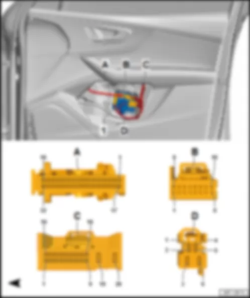
| -T32d- (A) | Designation | | -T16f- (B) | Designation |
| 1 | | | 1 | |
| 2 | | | 2 | Front passenger side automatic anti-dazzle exterior mirror -Y21- |
| 3 | Light for front passenger side interior door handle illumination -L220- | | 3 | Front passenger side turn signal repeater bulb -L132- /heated exterior mirror on front passenger side -Z5- |
| 4 | Terminal 58s, to R53 connection (58s) in front passenger door wiring harness
Front passenger side interior locking button for central locking system -E309-
Front passenger side operating unit for memory settings -E465-
Front passenger side window regulator button -E716- | | 4 | Earth, to 107 earth connection in exterior mirror wiring harness
Potentiometer for horizontal adjustment of front passenger side mirror -G516- /Potentiometer for vertical adjustment of front passenger side mirror -G517-
Lane change assist warning lamp in front passenger side exterior mirror -K234- |
| 5 | Earth, to 268 earth connection 2 in front passenger door wiring harness
Front passenger side interior locking button for central locking system -E309-
Front passenger side operating unit for memory settings -E465-
Front passenger side window regulator button -E716-
Light for front passenger side interior door handle illumination -L220-
Light for passenger door ambient lighting -W87-
Light 2 for front passenger door ambient lighting -W98-
Front passenger door exit warning light -W112-
405 earth connection 4 in front passenger door wiring harness
Light for passenger side door loudspeaker trim -L224-
Front passenger side door warning light -W36-
Front passenger side entry light -W93- | | 5 | Front passenger side mirror adjustment motor -V25- /front passenger side mirror adjustment motor -V150- |
| 6 | Front passenger door exit warning light -W112- | | 6 | Front passenger side automatic anti-dazzle exterior mirror -Y21- |
| 7 | | | 7 | Front passenger side mirror adjustment motor -V25- |
| 8 | to R99 connection 2 in front passenger door wiring harness
Light for passenger side door loudspeaker trim -L224-
Light for passenger door ambient lighting -W87-
Light 2 for front passenger door ambient lighting -W98- | | 8 | Front passenger side mirror adjustment motor -V150- |
| 9 | | | 9 | Front passenger side fold-in mirror motor -V122- |
| 10 | | | 10 | Front passenger side fold-in mirror motor -V122- |
| 11 | | | 11 | Front passenger side turn signal repeater bulb -L132- |
| 12 | | | 12 | Lane change assist warning lamp in front passenger side exterior mirror -K234- |
| 13 | Front passenger side interior locking button for central locking system -E309- | | 13 | Potentiometer for horizontal adjustment of front passenger side mirror -G516- |
| 14 | | | 14 | Potentiometer for horizontal adjustment of front passenger side mirror -G516- /Potentiometer for vertical adjustment of front passenger side mirror -G517- |
| 15 | Front passenger side operating unit for memory settings -E465-
Front passenger seat memory function button -E340- | | 15 | Heated exterior mirror on front passenger side -Z5- |
| 16 | to R100 connection 3 in front passenger door wiring harness
Front passenger side door warning light -W36-
Front passenger side entry light -W93- | | 16 | Front passenger side potentiometer for vertical mirror adjustment -G517- |
| 17 | Front passenger side operating unit for memory settings -E465- | | | |
| 18 | | | | |
| 19 | Front passenger side operating unit for memory settings -E465-
Seat memory position button 1 in front passenger door -E513- /seat memory position button 2 in front passenger door -E514- | | | |
| 20 | | | | |
| 21 | | | | |
| 22 | | | | |
| 23 | | | | |
| 24 | | | | |
| 25 | | | | |
| 26 | | | | |
| 27 | | | | |
| 28 | Front passenger side interior locking button for central locking system -E309- | | | |
| 29 | | | | |
| 30 | | | | |
| 31 | | | | |
| 32 | Front passenger side window regulator button -E716- | | | |
| -T20i- (C) | Designation | | -T6ar- (D) | Designation |
| 1 | | | 1 | |
| 2 | Front passenger side central locking lock unit -F221- | | 2 | |
| 3 | Front right door exterior handle illumination bulb -L163- | | 3 | Front passenger side window regulator motor -V148- |
| 4 | Front passenger side central locking lock unit -F221- | | 4 | |
| 5 | Front passenger side central locking lock unit -F221- | | 5 | Front passenger door power latching motor -V303- |
| 6 | Front passenger side central locking lock unit -F221- | | 6 | Front passenger side window regulator motor -V148- |
| 7 | Front passenger door power latching motor -V303- | | | |
| 8 | | | | |
| 9 | | | | |
| 10 | LIN bus, to coupling point on front right door -TTVR-
Coupling point on rear right door -TTHR-
Rear passenger side door control unit -J927- | | | |
| 11 | Front passenger side central locking lock unit -F221-
Front passenger door central locking SAFELOCK function motor -V162- /central locking motor on front passenger side -V504- | | | |
| 12 | Front passenger side central locking lock unit -F221-
Front passenger door central locking SAFELOCK function motor -V162- | | | |
| 13 | Front passenger side central locking lock unit -F221-
Front passenger side central locking motor -V504- | | | |
| 14 | Convenience CAN bus, low, from coupling point on front right door -TTVR-
B411 Connection 6 (convenience CAN bus, low) in main wiring harness
B406 Connection 1 (convenience CAN bus, low) in main wiring harness
Data bus diagnostic interface -J533- | | | |
| 15 | Convenience CAN bus, high, from coupling point on front right door -TTVR-
B402 Connection 6 (convenience CAN bus, high) in main wiring harness
B397 Connection 1 (convenience CAN bus, high) in main wiring harness
Data bus diagnostic interface -J533- | | | |
| 16 | Light for sill panel moulding ambient lighting, front passenger side -W103- | | | |
| 17 | | | | |
| 18 | | | | |
| 19 | Terminal 30, from R16 positive connection 1 (30) in front passenger door wiring harness
Coupling point on front right door -TTVR-
Fuse carrier 5 -ST5- in fuse holder B -SB- | | | |
| 20 | Terminal 31, to 206 earth connection in front passenger door wiring harness
Coupling point on front right door -TTVR-
394 Earth connection 29 in main wiring harness
638 Earth point on right A-pillar | | | |
| -T54b- (A) | Designation | | -T73a- (B) | Designation | | -T73b- (C) | Designation |
| 1 | Entry and start authorisation button -E408- | | 1 | 12 V sockets -U5- /-U18- /-U19- /-U20- | | 1 | Terminal 30, from fuse carrier 3 -ST3- in fuse holder B -SB- |
| 2 | Front right footwell illumination bulb -L152- | | 2 | Terminal 30, from fuse carrier 5 -ST5- in fuse holder B -SB- | | 2 | Headlight washer system pump -V11- |
| 3 | Front left footwell illumination bulb -L151- | | 3 | | | 3 | Washer pump -V5- /rear window wiper motor -V12- |
| 4 | | | 4 | | | 4 | Washer pump -V5- /rear window wiper motor -V12- |
| 5 | | | 5 | | | 5 | Treble horn -H2- /bass horn -H7- |
| 6 | | | 6 | | | 6 | |
| 7 | | | 7 | Terminal 15, from B450 connection 1 (PDC) in main wiring harness
Fuse carrier 4 -ST4- in fuse holder B -SB- | | 7 | |
| 8 | | | 8 | Air conditioning system magnetic clutch -N25- | | 8 | |
| 9 | | | 9 | | | 9 | Heating resistors for nozzles -Z20- /-Z21- /-Z114- |
| 10 | | | 10 | | | 10 | Front right heated seat backrest -Z117- |
| 11 | Earth, to centre dash panel switch module -EX22- | | 11 | Rear left footwell illumination bulb -L106- /rear right footwell illumination bulb -L107- | | 11 | Heated front passenger seat -Z8- /front passenger seat lateral support heater -Z33- /heated seat extension for front passenger seat -Z38- |
| 12 | | | 12 | Terminal 30, from fuse carrier 5 -ST5- in fuse holder B -SB- | | 12 | Terminal 30, from fuse carrier 5 -ST5- in fuse holder B -SB- |
| 13 | | | 13 | | | 13 | |
| 14 | | | 14 | | | 14 | |
| 15 | | | 15 | | | 15 | |
| 16 | | | 16 | Air conditioner compressor regulating valve -N280- | | 16 | Earth, to 348 earth connection (parking aid), in front bumper wiring harness
Front parking aid sender -G252- /-G253- /-G254- /-G255-
Front park assist steering sender -G568- /-G569- |
| 17 | | | 17 | Auto-hold warning lamp -K237- | | 17 | Earth, to 352 earth connection (parking aid), in rear bumper wiring harness
Rear parking aid sender -G203- /-G204- /-G205- /-G206-
Rear park assist steering sender -G716- /-G717- |
| 18 | LIN bus, to control unit for electrically adjustable steering column -J866- | | 18 | | | 18 | Front left parking aid sender -G255- |
| 19 | Front parking aid warning buzzer -H22- | | 19 | Terminal 15, to B281 positive connection 5 (15a) in main wiring harness | | 19 | Supply, to X65 connection (parking aid), in front bumper wiring harness
Front parking aid sender -G252- /-G253- /-G254- /-G255-
Front park assist steering sender -G568- /-G569- |
| 20 | Front parking aid warning buzzer -H22- | | 20 | Front left brake pad wear sender -G34- | | 20 | Supply, to X68 connection (parking aid), in rear bumper wiring harness
Rear parking aid sender -G203- /-G204- /-G205- /-G206-
Rear park assist steering sender -G716- /-G717- |
| 21 | | | 21 | Brake fluid level warning contact -F34- | | 21 | Front right parking aid sender -G252- |
| 22 | | | 22 | LIN bus, to wiper motor control unit -J400- | | 22 | Front centre right parking aid sender -G253- |
| 23 | | | 23 | LIN bis. to rain and light sensor -G397- | | 23 | Front left seat temperature sender -G344- |
| 24 | | | 24 | LIN bus, to B549 connection 2 (LIN bus) in main wiring harness
Garage door operating unit -E284-
Roof electronics control unit -J528-
Garage door operation control unit -J530-
Automatic anti-dazzle interior mirror -Y7- | | 24 | |
| 25 | | | 25 | LIN bus, to seat fans -V388- /-V389- /-V390- /-V391- | | 25 | Front left backrest temperature sensor -G806- |
| 26 | | | 26 | | | 26 | Front right seat temperature sender -G345- |
| 27 | | | 27 | LIN bus, to B711 connection 6 (LIN bus) in main wiring harness
Light for front left door contour lighting -L251-
Light for front right door contour lighting -L252-
Light for rear left door contour lighting -L253-
Light for rear right door contour lighting -L254-
Light conductor for front centre console ambient lighting -W74- | | 27 | Front right backrest temperature sensor -G807- |
| 28 | | | 28 | LIN bus (ambient lighting), to dash panel contour illumination light 3 -L245- | | 28 | |
| 29 | | | 29 | | | 29 | |
| 30 | LIN bus, to light switch -E1- | | 30 | Bonnet contact switch 2 -F329- | | 30 | |
| 31 | | | 31 | Bonnet contact switch -F266- | | 31 | Auto-hold button -E540- |
| 32 | | | 32 | Terminal 58s, to B732 connection 2 (58s) in main wiring harness
B731 connection 1 (58s) in main wiring harness | | 32 | |
| 33 | | | 33 | | | 33 | |
| 34 | | | 34 | Terminal 58s, to roof electronics control unit -J528- | | 34 | |
| 35 | | | 35 | Rear parking aid warning buzzer -H15- | | 35 | |
| 36 | | | 36 | Supply, to A138 connection 2 in dash panel wiring harness
Light 1 for dash panel contour lighting -L243-
Light 2 for dash panel contour lighting -L244- | | 36 | |
| 37 | Terminal 58s, to A3 positive connection (58) in dash panel wiring harness
A175 connection (58s), in dash panel wiring harness
B732 connection 2 (58s) in main wiring harness 1) | | 37 | | | 37 | |
| 38 | | | 38 | Air conditioner compressor regulating valve -N280- | | 38 | |
| 39 | Glove compartment light -W6- | | 39 | | | 39 | |
| 40 | | | 40 | Earth, to 410 earth connection 1 (sender earth) in main wiring harness | | 40 | Convenience CAN bus, high, from B398 connection 2 (convenience CAN bus, high) in main wiring harness
B402 Connection 6 (convenience CAN bus, high) in main wiring harness
B397 Connection 1 (convenience CAN bus, high) in main wiring harness
Data bus diagnostic interface -J533- |
| 41 | | | 41 | | | 41 | Convenience CAN bus, low, to B407 connection 2 (convenience CAN bus, low) in main wiring harness
B411 Connection 6 (convenience CAN bus, low) in main wiring harness
B406 Connection 1 (convenience CAN bus, low) in main wiring harness
Data bus diagnostic interface -J533- |
| 42 | | | 42 | Extended low CAN bus, to B109 connection 1 (extended low CAN bus) in main wiring harness
Front left headlight -MX1-
Front camera for driver assist systems -R242- | | 42 | Extended high CAN bus, to front right headlight -MX2- |
| 43 | | | 43 | Extended high CAN bus, to B108 connection 1 (extended high CAN bus) in main wiring harness
Front left headlight -MX1-
Front camera for driver assist systems -R242- | | 43 | Extended low CAN bus, to front right headlight -MX2- |
| 44 | | | 44 | Windscreen washer fluid level sender -G33- | | 44 | |
| 45 | | | 45 | Coolant shortage indicator sender -G32- | | 45 | |
| 46 | | | 46 | Ambient temperature sensor -G17- | | 46 | Seat heating control unit -J882- |
| 47 | | | 47 | | | 47 | |
| 48 | | | 48 | | | 48 | Front centre left parking aid sender -G254- |
| 49 | | | 49 | | | 49 | |
| 50 | LIN bus, to light switch -E1- | | 50 | | | 50 | Front right sender for park assist steering on right side of vehicle -G569- |
| 51 | Lin bus, to centre dash panel switch module -EX22- | | 51 | | | 51 | Front left sender for park assist steering on left side of vehicle -G568- |
| 52 | | | 52 | | | 52 | Rear right parking aid sender -G206- |
| 53 | LIN bus, to dash panel contour illumination light 1 -L243- | | 53 | Rear parking aid warning buzzer -H15- | | 53 | Rear left parking aid sender -G203- |
| 54 | | | 54 | | | 54 | |
| | | | 55 | | | 55 | Rear centre right parking aid sender -G205- |
| | | | 56 | | | 56 | Rear centre left parking aid sender -G204- |
| | | | 57 | | | 57 | Rear right park assist steering sender -G717- |
| | | | 58 | | | 58 | Rear left park assist steering sender -G716- |
| | | | 59 | Ambient light power supply, to B470 connection 6 in main wiring harness | | 59 | |
| | | | 60 | | | 60 | |
| | | | 61 | | | 61 | |
| | | | 62 | | | 62 | |
| | | | 63 | Terminal 31, to 369 earth connection 4 in main wiring harness
645 Earth point 1, on bulkhead | | 63 | Terminal 31, to 369 earth connection 4 in main wiring harness
645 Earth point 1, on bulkhead |
| | | | 64 | Front left headlight -MX1- | | 64 | Front right headlight -MX2- |
| | | | 65 | Front left headlight -MX1- | | 65 | Front right headlight -MX2- |
| | | | 66 | Terminal 30, from fuse carrier 3 -ST3- in fuse holder B -SB- | | 66 | Terminal 30, from fuse carrier 3 -ST3- in fuse holder B -SB- |
| | | | 67 | Front right headlight -MX2- | | 67 | Front left headlight -MX1- |
| | | | 68 | | | 68 | |
| | | | 69 | | | 69 | |
| | | | 70 | | | 70 | |
| | | | 71 | | | 71 | Heated front passenger seat -Z6- /driver seat cushion lateral support heater -Z31- /heated seat extension for driver seat -Z37- |
| | | | 72 | Illuminated vanity mirror -W14- /-W20- | | 72 | Front left heated seat backrest -Z116- |
| | | | 73 | Terminal 30, from fuse carrier 3 -ST3- in fuse holder B -SB- | | 73 | Terminal 30, from fuse carrier 3 -ST3- in fuse holder B -SB- |
| -T54a- (A) | Designation | | -T54a- (A) | Designation | | -T54a- (A) | Designation |
| 1 | | | 19 | | | 37 | |
| 2 | | | 20 | | | 38 | |
| 3 | FlexRay bus, to diagnostic connection -U31- | | 21 | FlexRay bus, to diagnostic connection -U31- | | 39 | |
| 4 | FlexRay bus, to diagnostic connection -U31- | | 22 | FlexRay bus, to diagnostic connection -U31- | | 40 | |
| 5 | FlexRay bus, to all-wheel drive control unit -J492-1)
Rear wheel steering control unit -J1019-2) | | 23 | FlexRay bus, to all-wheel drive control unit -J492-1)
Rear wheel steering control unit -J1019-2) | | 41 | FlexRay bus, from all-wheel drive control unit -J492- |
| 6 | | | 24 | | | 42 | FlexRay bus, from all-wheel drive control unit -J492- |
| 7 | FlexRay bus, to control unit 2 for adaptive cruise control -J850- | | 25 | FlexRay bus, to control unit 2 for adaptive cruise control -J850- | | 43 | |
| 8 | FlexRay bus, to airbag control unit -J234- | | 26 | FlexRay bus, to airbag control unit -J234- | | 44 | |
| 9 | FlexRay bus, to automatic gearbox control unit -J217- | | 27 | FlexRay bus, to automatic gearbox control unit -J217- | | 45 | FlexRay bus, to steering column electronics control unit -J527-3) or
front camera for driver assist systems -R242-4) or
running gear control unit -J775-5) |
| 10 | FlexRay bus, to engine control unit -J623- | | 28 | FlexRay bus, to engine control unit -J623- | | 46 | FlexRay bus, to steering column electronics control unit -J527-3) or
front camera for driver assist systems -R242-4) or
running gear control unit -J775-5) |
| 11 | Drive high CAN bus to B383 connection 1 (drive high CAN bus) in main wiring harness | | 29 | Drive low CAN bus, to B390 connection 1 (drive low CAN bus) in main wiring harness | | 47 | |
| 12 | Extended high CAN bus, to B670 connection 3 (extended high CAN bus) in main wiring harness | | 30 | Extended low CAN bus, to B671 connection 3 (extended low CAN bus) in main wiring harness | | 48 | Diagnostic low CAN bus, to diagnostic connection -U31- |
| 13 | Infotainment high CAN bus, to A178 connection (infotainment high CAN bus) in dash panel wiring harness | | 31 | Infotainment low CAN bus, to A179 connection (infotainment low CAN bus) in dash panel wiring harness | | 49 | Diagnostic high CAN bus, to diagnostic connection -U31- |
| 14 | | | 32 | | | 50 | Drive low CAN bus, to B391 connection 2 (drive low CAN bus) in main wiring harness |
| 15 | Convenience CAN bus, high, to B397 connection 1 (convenience CAN bus, high) in main wiring harness | | 33 | Convenience CAN bus, low, to B406 connection 1 (convenience CAN bus, low) in main wiring harness | | 51 | Drive high CAN bus to B384 connection 2 (drive high CAN bus) in main wiring harness |
| 16 | LIN bus, to B699 connection 4 (LIN bus) in main wiring harness
Battery monitor control unit -J367-
Alternator -C- | | 34 | LIN bus, to steering column electronics control unit -J527- | | 52 | |
| 17 | Terminal 15, from B450 connection 1 (PDC) in main wiring harness
Fuse carrier 4 -ST4- in fuse holder B -SB- | | 35 | | | 53 | |
| 18 | Terminal 30, from fuse carrier 5 -ST5- in fuse holder B -SB- | | 36 | Diagnostic connection -U31- | | 54 | Earth, to 79 earth point on left B-pillar |
| -T54a- (C) | Designation | | -T54a- (C) | Designation | | -T54a- (C) | Designation |
| 1 | | | 19 | | | 37 | |
| 2 | | | 20 | | | 38 | |
| 3 | FlexRay bus, to diagnostic connection -U31- | | 21 | FlexRay bus, to diagnostic connection -U31- | | 39 | |
| 4 | FlexRay bus, to diagnostic connection -U31- | | 22 | FlexRay bus, to diagnostic connection -U31- | | 40 | |
| 5 | FlexRay bus, to all-wheel drive control unit -J492-1)
Rear wheel steering control unit -J1019-2) | | 23 | FlexRay bus, to all-wheel drive control unit -J492-1)
Rear wheel steering control unit -J1019-2) | | 41 | FlexRay bus, from all-wheel drive control unit -J492- |
| 6 | | | 24 | | | 42 | FlexRay bus, from all-wheel drive control unit -J492- |
| 7 | FlexRay bus, to control unit 2 for adaptive cruise control -J850- | | 25 | FlexRay bus, to control unit 2 for adaptive cruise control -J850- | | 43 | |
| 8 | FlexRay bus, to airbag control unit -J234- | | 26 | FlexRay bus, to airbag control unit -J234- | | 44 | |
| 9 | FlexRay bus, to automatic gearbox control unit -J217- | | 27 | FlexRay bus, to automatic gearbox control unit -J217- | | 45 | FlexRay bus, to steering column electronics control unit -J527-3) or
front camera for driver assist systems -R242-4) or
running gear control unit -J775-5) |
| 10 | FlexRay bus, to engine control unit -J623- | | 28 | FlexRay bus, to engine control unit -J623- | | 46 | FlexRay bus, to steering column electronics control unit -J527-3) or
front camera for driver assist systems -R242-4) or
running gear control unit -J775-5) |
| 11 | Drive high CAN bus to B383 connection 1 (drive high CAN bus) in main wiring harness | | 29 | Drive low CAN bus, to B390 connection 1 (drive low CAN bus) in main wiring harness | | 47 | |
| 12 | Extended high CAN bus, to B670 connection 3 (extended high CAN bus) in main wiring harness | | 30 | Extended low CAN bus, to B671 connection 3 (extended low CAN bus) in main wiring harness | | 48 | Diagnostic low CAN bus, to diagnostic connection -U31- |
| 13 | Infotainment high CAN bus, to A178 connection (infotainment high CAN bus) in dash panel wiring harness | | 31 | Infotainment low CAN bus, to A179 connection (infotainment low CAN bus) in dash panel wiring harness | | 49 | Diagnostic high CAN bus, to diagnostic connection -U31- |
| 14 | | | 32 | | | 50 | Drive low CAN bus, to B391 connection 2 (drive low CAN bus) in main wiring harness |
| 15 | Convenience CAN bus, high, to B397 connection 1 (convenience CAN bus, high) in main wiring harness | | 33 | Convenience CAN bus, low, to B406 connection 1 (convenience CAN bus, low) in main wiring harness | | 51 | Drive high CAN bus to B384 connection 2 (drive high CAN bus) in main wiring harness |
| 16 | LIN bus, to B699 connection 4 (LIN bus) in main wiring harness
Battery monitor control unit -J367-
Alternator -C- | | 34 | LIN bus, to steering column electronics control unit -J527- | | 52 | |
| 17 | Terminal 15, from B450 connection 1 (PDC) in main wiring harness
Fuse carrier 4 -ST4- in fuse holder B -SB- | | 35 | | | 53 | |
| 18 | Terminal 30, from fuse carrier 5 -ST5- in fuse holder B -SB- | | 36 | Diagnostic connection -U31- | | 54 | Earth, to 79 earth point on left B-pillar |
| -T81a- (A) | Designation | | -T81a- (A) | Designation | | -T81a- (A) | Designation |
| 1 | Terminal 30, from fuse carrier 1 -ST1- in fuse holder F -SF- | | 28 | Operating unit for lowering load sill -E682-
Loading height button -E539- | | 55 | |
| 2 | | | 29 | Earth, to operating unit for lowering load sill -E682-
Loading height button -E539- | | 56 | |
| 3 | | | 30 | | | 57 | |
| 4 | | | 31 | Front right vehicle level sender -G289- | | 58 | |
| 5 | Terminal 31, to 602 earth point on left in footwell | | 32 | Rear left vehicle level sender -G76- | | 59 | Adaptive suspension drain valve -N111- |
| 6 | Running gear sensors high CAN bus, from B663 connection (running gear sensors high CAN bus) in main wiring harness | | 33 | Valve block for adaptive suspension -NX7-
Rear right suspension strut valve -N151- | | 60 | |
| 7 | | | 34 | Front right vehicle level sender -G289- | | 61 | |
| 8 | Valve block for adaptive suspension -NX7-
Pressure sender for adaptive suspension -G291- | | 35 | Valve block for adaptive suspension -NX7-
Rear left suspension strut valve -N150- | | 62 | Terminal 15, from B281 positive connection 5 (15a) in main wiring harness
Onboard supply control unit -J519- |
| 9 | Front left vehicle level sender -G78- | | 36 | Compressor temperature sender for adaptive suspension -G290- | | 63 | FlexRay bus, to front camera for driver assist systems -R242-1) or
to steering column electronics control unit -J527-2) |
| 10 | Front left vehicle level sender -G78- | | 37 | Valve block for adaptive suspension -NX7-
Front left suspension strut valve -N148- | | 64 | FlexRay bus, to front camera for driver assist systems -R242-1) or
to steering column electronics control unit -J527-2) |
| 11 | Front left vehicle level sender -G78- | | 38 | | | 65 | |
| 12 | Front right vehicle level sender -G289- | | 39 | | | 66 | |
| 13 | Rear left vehicle level sender -G76- | | 40 | | | 67 | Operating unit for lowering load sill -E682-
Loading height button -E539- |
| 14 | Rear left vehicle level sender -G76- | | 41 | | | 68 | Rear right shock absorber damping adjustment valve -N339- |
| 15 | | | 42 | | | 69 | Rear right shock absorber damping adjustment valve -N339- |
| 16 | Compressor temperature sender for adaptive suspension -G290- | | 43 | | | 70 | |
| 17 | Rear right vehicle level sender -G77- | | 44 | FlexRay bus, from data bus diagnostic interface -J533- | | 71 | Operating unit for lowering load sill -E682-
Loading height button -E539- |
| 18 | Rear right vehicle level sender -G77- | | 45 | FlexRay bus, from data bus diagnostic interface -J533- | | 72 | Rear left shock absorber damping adjustment valve -N338- |
| 19 | Rear right vehicle level sender -G77- | | 46 | | | 73 | Rear left shock absorber damping adjustment valve -N338- |
| 20 | | | 47 | | | 74 | |
| 21 | | | 48 | | | 75 | Valve block for adaptive suspension -NX7-
Front right suspension strut valve -N149- |
| 22 | | | 49 | Operating unit for lowering load sill -E682-
Loading height button -E539- | | 76 | Front right shock absorber damping adjustment valve -N337- |
| 23 | | | 50 | | | 77 | Front right shock absorber damping adjustment valve -N337- |
| 24 | | | 51 | | | 78 | Adaptive suspension drain valve -N111- |
| 25 | Running gear sensors low CAN bus, from B664 connection (running gear sensors low CAN bus) in main wiring harness | | 52 | | | 79 | Adaptive suspension drain valve -N111- |
| 26 | Valve block for adaptive suspension -NX7-
Pressure sender for adaptive suspension -G291- | | 53 | Valve block for adaptive suspension -NX7-
Adaptive suspension pressure accumulator valve -N311- | | 80 | Front left shock absorber damping adjustment valve -N336- |
| 27 | Valve block for adaptive suspension -NX7-
Pressure sender for adaptive suspension -G291- | | 54 | Valve block for adaptive suspension -NX7-
Front left suspension strut valve -N148-
Front right suspension strut valve -N149-
Rear left suspension strut valve -N150-
Rear right suspension strut valve -N151-
Adaptive suspension pressure accumulator valve -N311- | | 81 | Front left shock absorber damping adjustment valve -N336- |
| -T8i- (D) | Designation | | -T12n- (E) | Designation | | -T12o- (F) | Designation |
| 9 | Subwoofer -R211- | | 1 | CAN bus, control unit 1 for information electronics, high, to E145 connection 1 (CAN bus, control unit 1 for information electronics, high)
Multimedia system operating unit -E380-
Pivot mechanism for display -VX452- | | 1 | Connection for external audio sources -R199- , AUX IN earth |
| 10 | Centre loudspeaker -R208- /central loudspeaker 2 -R219- | | 2 | Multimedia system operating unit -E380- | | 2 | Connection for external audio sources -R199- , AUX IN right |
| 11 | | | 3 | Ring circuit break diagnostic | | 3 | Connection for external audio sources -R199- , USB 5V |
| 12 | | | 4 | | | 4 | Connection for external audio sources -R199- , USB earth |
| 13 | Subwoofer -R211- | | 5 | Telephone bracket -R126- /aerial amplifier for mobile telephone -R86- | | 5 | |
| 14 | Centre loudspeaker -R208- /central loudspeaker 2 -R219- | | 6 | Infotainment CAN bus, high, from A178 connection (infotainment CAN bus, high) in dash panel wiring harness
Coupling point on left A-pillar, bottom -TALU-
Data bus diagnostic interface -J533- | | 6 | |
| 17 | Terminal 31, to 752 earth point 3 on right A-pillar1)
687 Earth point 1 on centre tunnel2) | | 7 | CAN bus, control unit 1 for information electronics, low, to E147 connection 1 (CAN bus, control unit 1 for information electronics, low)
Multimedia system operating unit -E380-
Pivot mechanism for display -VX452- | | 7 | Connection for external audio sources -R199- , AUX IN left |
| 18 | Terminal 30, from fuse holder C -SC- | | 8 | Multimedia system operating unit -E380- | | 8 | Connection for external audio sources -R199- , screen earth |
| | | | 9 | | | 9 | |
| | | | 10 | | | 10 | |
| | | | 11 | Telephone bracket -R126- | | 11 | |
| | | | 12 | Infotainment CAN bus, low, from A179 connection (infotainment CAN bus, low) in dash panel wiring harness
Coupling point on left A-pillar, bottom -TALU-
Data bus diagnostic interface -J533- | | 12 | |
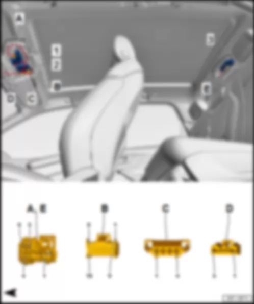
| -T20k- (C) | Designation | | -T6al- (D) | Designation |
| 1 | Light for rear driver side exterior door handle illumination -L285- | | 1 | |
| 2 | Rear central locking actuator, driver side -F509- | | 2 | |
| 3 | | | 3 | Rear driver side window regulator motor -V471- |
| 4 | Rear central locking actuator, driver side -F509- | | 4 | |
| 5 | Rear central locking actuator, driver side -F509- | | 5 | |
| 6 | Rear central locking actuator, driver side -F509- | | 6 | Rear driver side window regulator motor -V471- |
| 7 | Rear left power latching motor -V307- | | | |
| 8 | | | | |
| 9 | Rear central locking actuator, driver side -F509-
Rear driver side childproof lock motor -V535- | | | |
| 10 | LIN bus, from coupling point on rear left door -TTHL-
Coupling point on front left door -TTVL-
Driver door control unit -J386- | | | |
| 11 | Rear central locking actuator, driver side -F509-
Rear childproof lock motor, driver side -V535- /rear central locking SAFELOCK function motor, driver side -V537- /rear central locking motor, driver side -V539- | | | |
| 12 | Rear central locking actuator, driver side -F509-
Rear driver side door central locking SAFELOCK function motor -V537- | | | |
| 13 | Rear central locking actuator, driver side -F509-
Rear driver side door central locking motor -V539- | | | |
| 14 | Rear left power latching motor -V307- | | | |
| 15 | Light for rear sill panel moulding ambient lighting, driver side -W105- | | | |
| 16 | | | | |
| 17 | Rear central locking actuator, driver side -F509- | | | |
| 18 | | | | |
| 19 | Terminal 30, from R31 connection 1 in rear left door wiring harness
Coupling point on rear left door -TTHL-
Fuse carrier 3 -ST3- in fuse holder B -SB- | | | |
| 20 | Terminal 31, to 207 earth connection in rear left door wiring harness
Coupling point on rear left door -TTHL-
379 Earth connection 14 in main wiring harness
79 Earth point, on left B-pillar | | | |
| -T20l- (C) | Designation | | -T6am- (D) | Designation |
| 1 | Light for rear passenger side exterior door handle illumination -L286- | | 1 | |
| 2 | Rear central locking actuator, passenger side -F510- | | 2 | |
| 3 | | | 3 | Rear passenger side window regulator motor -V472- |
| 4 | Rear central locking actuator, passenger side -F510- | | 4 | |
| 5 | Rear central locking actuator, passenger side -F510- | | 5 | |
| 6 | Rear central locking actuator, passenger side -F510- | | 6 | Rear passenger side window regulator motor -V472- |
| 7 | Rear right power latching motor -V308- | | | |
| 8 | | | | |
| 9 | Rear central locking actuator, passenger side -F510-
Rear passenger side childproof lock motor -V536- | | | |
| 10 | LIN bus, from coupling point on rear right door -TTHR-
Coupling point on front right door -TTVR-
Front passenger door control unit -J387- | | | |
| 11 | Rear central locking actuator, passenger side -F510-
Rear childproof lock motor, passenger side -V536- /rear central locking SAFELOCK function motor, passenger side -V538- /rear central locking motor, passenger side -V540- | | | |
| 12 | Rear central locking actuator, passenger side -F510-
Rear passenger side door central locking SAFELOCK function motor -V538- | | | |
| 13 | Rear central locking actuator, passenger side -F510-
Rear passenger side door central locking motor -V540- | | | |
| 14 | Rear right power latching motor -V308- | | | |
| 15 | Light for rear sill panel moulding ambient lighting, front passenger side -W104- | | | |
| 16 | | | | |
| 17 | Rear central locking actuator, passenger side -F510- | | | |
| 18 | | | | |
| 19 | Terminal 30, from R32 connection 2 in rear right door wiring harness
Coupling point on rear right door -TTHR-
Fuse carrier 3 -ST3- in fuse holder B -SB- | | | |
| 20 | Terminal 31, to 208 earth connection in rear right door wiring harness
Coupling point on rear right door -TTHR-
381 Earth connection 16 in main wiring harness
720 Earth point, on right B-pillar | | | |
| No. | | Current flow diagram designation | Nominal value | | Function/component | Terminal |
| 1 | - | Not assigned | | - | | |
| 2 | - | Not assigned | | - | | |
| 3 | - | Fuse 3 on fuse holder B -SB3- | 15 A | - | Injector 2 for cylinder -N532- … -N537- | 87 |
| 4 | - | Fuse 4 on fuse holder B -SB4- | 7.5 A | - | Coolant circulation pump -V50- | 87 |
| 5 | - | Fuse 5 on fuse holder B -SB5- | 5 A | - | Brake light switch -F- | 87 |
| 6 | - | Fuse 6 on fuse holder B -SB6- | 15 A | - | Activated charcoal filter solenoid valve 1 -N80-
Secondary air inlet valve -N112-
Valve for oil pressure control -N428-
Coolant valve for cylinder head -N489-
Solenoid valve for coolant circuit -N492-
Crankcase breather shut-off valve -N548- | 87 |
| 7 | - | Fuse 7 on fuse holder B -SB7- | 20 A | - | Lambda probe 1 heater after catalytic converter -Z29-
Lambda probe 2 heater after catalytic converter -Z30- | 87 |
| 8 | - | Fuse 8 on fuse holder B -SB8- | 7.5 A | - | Secondary air pump relay -J299-
Left electrohydraulic engine mounting solenoid valve -N144-
Right electrohydraulic engine mounting solenoid valve -N145-
Charge air cooling pump -V188-
Radiator blind control motor -V544- | 87 |
| 9 | - | Fuse 9 on fuse holder B -SB9- | 5 A | - | Engine component current supply relay -J757- | 87 |
| 10 | - | Fuse 10 on fuse holder B -SB10- | 5 A | - | Oil level and oil temperature sender -G266- | 87 |
| 11 | - | Not assigned | | - | | |
| 12 | - | Fuse 12 on fuse holder B -SB12- | 10 A | - | Camshaft control valve 1 -N205-
Camshaft control valve 2 -N208-
Air filter bypass flap valve -N275-
Intake manifold flap valve -N316-
Exhaust camshaft control valve 1 -N318-
Exhaust camshaft control valve 2 -N319- | 87 |
| 13 | - | Fuse 13 on fuse holder B -SB13- | 5 A | - | Radiator fan control unit -J293-
Radiator fan control unit 2 -J671- | 87 |
| 14 | - | Fuse 14 on fuse holder B -SB14- | 25 A | - | Engine control unit -J623- | 87 |
| 15 | - | Fuse 15 on fuse holder B -SB15- | 20 A | - | Lambda probe heater -Z19-
Lambda probe heater 2 -Z28- | 87 |
| 16 | - | Fuse 16 on fuse holder B -SB16- | 30 A | - | Fuel pump control unit -J538- | 87 |
| No. | | Current flow diagram designation | Nominal value | | Function/component | Terminal |
| 1 | - | Not assigned | | - | | |
| 2 | - | Not assigned | | - | | |
| 3 | - | Not assigned | | - | | |
| 4 | - | Fuse 4 on fuse holder B -SB4- | 5 A1)
7.5 A2) | - | Exhaust flap control unit -J883-2)
Solenoid valve 7 -N94-2)
Coolant circulation pump -V50-1) | 87 |
| 5 | - | Fuse 5 on fuse holder B -SB5- | 5 A1) | - | Brake light switch -F-1) | 87 |
| 6 | - | Fuse 6 on fuse holder B -SB6- | 15 A | - | Actuator for camshaft adjustment -F366- … -F373-
| 87 |
| 7 | - | Fuse 7 on fuse holder B -SB7- | 15 A | - | Lambda probe 1 heater after catalytic converter -Z29- | 87 |
| 8 | - | Fuse 8 on fuse holder B -SB8- | 5 A | - | Left electrohydraulic engine mounting solenoid valve -N144-1)
Right electrohydraulic engine mounting solenoid valve -N145-1)
Gearbox mounting valve 1 -N262-2)
Gearbox mounting valve 2 -N263-2)
Coolant valve for gearbox -N488-1)
Coolant circulation pump -V50-2)
Charge air cooling pump -V188-1) | 87 |
| 9 | - | Fuse 9 on fuse holder B -SB9- | 5 A | - | Engine component current supply relay -J757- | 87 |
| 10 | - | Fuse 10 on fuse holder B -SB10- | 5 A | - | Oil level and oil temperature sender -G266- | 87 |
| 11 | - | Not assigned | | - | | |
| 12 | - | Fuse 12 on fuse holder B -SB12- | 10 A | - | Activated charcoal filter solenoid valve 1 -N80-
Secondary air inlet valve -N112-1)
Camshaft control valve 1 -N205-
Turbocharger air recirculation valve -N249-
Air filter bypass flap valve -N275-
Intake manifold flap valve -N316-
Exhaust camshaft control valve 1 -N318-
Valve for oil pressure control -N428-
Piston cooling jet control valve -N522- | 87 |
| 13 | - | Fuse 13 on fuse holder B -SB13- | 5 A1) | - | Radiator fan control unit -J293-1)
Radiator fan control unit 2 -J671-1) | 87 |
| 14 | - | Fuse 14 on fuse holder B -SB14- | 15 A | - | Engine control unit -J623-
Injector 2 for cylinder -N532- … -N535- | 87 |
| 15 | - | Fuse 15 on fuse holder B -SB15- | 15 A | - | Lambda probe heater -Z19- | 87 |
| 16 | - | Fuse 16 on fuse holder B -SB16- | 30 A | - | Fuel pump control unit -J538- | 87 |
| No. | | Current flow diagram designation | Nominal value | | Function/component | Terminal |
| 1 | - | Fuse 1 on fuse holder B -SB1- | 5 A | - | Diagnostic connection -U31-
Main beam assist control unit -J844-
Operating and display unit for rear air conditioning system -E265-
Seat heating control unit -J882-
Driver seat backrest fan -V388-
Front passenger seat backrest fan -V389-
Driver seat cushion fan -V390-
Front passenger seat cushion fan -V391- | 15 |
| 2 | - | Fuse 2 on fuse holder B -SB2- | 10 A | - | Data bus diagnostic interface -J533-
Onboard supply control unit -J519- | 15 |
| 3 | - | Fuse 3 on fuse holder B -SB3- | 15 A1)
7.5 A2) | - | Control unit for structure-borne sound -J869-1)
Engine sound generator control unit -J943-2) | 15 |
| 4 | - | Fuse 4 on fuse holder B -SB4- | 5 A | - | Gearbox oil cooling valve -N509- | 15 |
| 5 | - | Fuse 5 on fuse holder B -SB5- | 5 A | - | Starter relay 1 -J906-1)
Starter relay 2 -J907-1)
Power and control electronics for electric drive -JX1-2) | 15 |
| 6 | - | Not assigned | | - | | |
| 7 | - | Fuse 7 on fuse holder B -SB7- | 5 A1)
10 A2) | - | 17-pin connector -T17b- in coupling point on left A-pillar, bottom -TALU-1)
Brake pedal position sender -G100-2) | 15 |
| 8 | - | Fuse 8 on fuse holder B -SB8- | 5 A | - | Driver-side ioniser -J1105-
Garage door operating unit -E284-
Control unit for night vision system -J853- | 15 |
| 9 | - | Fuse 9 on fuse holder B -SB9- | 10 A | - | Adaptive cruise control unit -J428-
Control unit 2 for adaptive cruise control -J850- | 15 |
| 10 | - | Not assigned | | - | | |
| 11 | - | Fuse 11 on fuse holder B -SB11- | 7.5 A | - | Front camera for driver assist systems -R242- | 15 |
| 12 | - | Fuse 12 on fuse holder B -SB12- | 10 A | - | Front right headlight -MX2- | 15 |
| 13 | - | Fuse 13 on fuse holder B -SB13- | 10 A | - | Front left headlight -MX1- | 15 |
| 14 | - | Fuse 14 on fuse holder B -SB14- | 20 A | - | Rear window wiper motor -V12- | 15 |
| 15 | - | Not assigned | | - | | |
| 16 | - | Not assigned | | - | | |
| No. | | Current flow diagram designation | Nominal value | | Function/component | Terminal |
| 1 | - | Not assigned | | - | | |
| 2 | - | Fuse 2 on fuse holder C -SC2- | 5 A | - | Chip card reader control unit -J676-
Telephone bracket -R126- | 30 |
| 3 | - | Not assigned | | - | | |
| 4 | - | Fuse 4 on fuse holder C -SC4- | 5 A | - | Control unit for heads-up display -J898- | 30 |
| 5 | - | Fuse 5 on fuse holder C -SC5- | 5 A | - | Connection for external audio sources -R199- | 30 |
| 6 | - | Fuse 6 on fuse holder C -SC6- | 10 A | - | Operating and display unit for front air conditioning system -E87- | 30 |
| 7 | - | Fuse 7 on fuse holder C -SC7- | 10 A | - | Control unit for electronic steering column lock -J764- | 30 |
| 8 | - | Fuse 8 on fuse holder C -SC8- | 5 A | - | Display unit for front information display and operating unit control unit -J685- /Pivot mechanism for display -VX452- | 30 |
| 9 | - | Fuse 9 on fuse holder C -SC9- | 10 A | - | Control unit in dash panel insert -J285- | 30 |
| 10 | - | Fuse 10 on fuse holder B -SB10- | 5 A | - | Multimedia system operating unit -E380- | 30 |
| 11 | - | Fuse 11 on fuse holder C -SC11- | 5 A | - | Light switch -E1-
Operating unit 1 for driving and comfort functions -E791- | 30 |
| 12 | - | Fuse 12 on fuse holder C -SC12- | 1 A | - | Steering column electronics control unit -J527- | 30 |
| 13 | - | Not assigned | | - | | |
| 14 | - | Fuse 14 on fuse holder C -SC14- | 20 A1)
5 A2) | - | Control unit 1 for information electronics -J794- | 30 |
| 15 | - | Fuse 15 on fuse holder C -SC15- | 25 A | - | Control unit for electrically adjustable steering column -J866- | 30 |
| 16 | - | Fuse 16 on fuse holder C -SC16- | 10 A | - | Steering column electronics control unit -J527- | 30 |
| -T46a- (A) | Designation | | -T46a- (A) | Designation |
| 1 | Terminal 30, from fuse holder H -SH- in fuse holder B -SB- | | 24 | Front left speed sensor -G47- |
| 2 | Right parking brake motor -V283- | | 25 | Electromechanical parking brake warning lamp -K213- |
| 3 | Right parking brake motor -V283- | | 26 | Front right speed sensor -G45- |
| 4 | Terminal 30, from fuse carrier 5 -ST5- in fuse holder B -SB- | | 27 | |
| 5 | | | 28 | Data bus line (FlexRay bus), from engine control unit -J623- |
| 6 | | | 29 | |
| 7 | Front left speed sensor -G47- | | 30 | Terminal 30, from fuse holder H -SH- in fuse holder B -SB- |
| 8 | Roof carrier detection sensor -G625- | | 31 | Electromechanical parking brake button -E538- |
| 9 | | | 32 | Electromechanical parking brake button -E538- |
| 10 | | | 33 | |
| 11 | | | 34 | |
| 12 | Left parking brake motor -V282- | | 35 | |
| 13 | Left parking brake motor -V282- | | 36 | Terminal 15, from B281 positive connection 5 (15a) in main wiring harness
Onboard supply control unit -J519- |
| 14 | Terminal 31, to 671 earth point 1 on front side member, left | | 37 | Rear right speed sensor -G44- |
| 15 | Electromechanical parking brake button -E538- | | 38 | |
| 16 | Electromechanical parking brake button -E538- | | 39 | Rear left speed sensor -G46- |
| 17 | | | 40 | Vacuum sender -G608- |
| 18 | Roof carrier detection sensor -G625- | | 41 | Vacuum sender -G608- |
| 19 | | | 42 | |
| 20 | | | 43 | |
| 21 | Front right speed sensor -G45- | | 44 | Data bus line (FlexRay bus), from engine control unit -J623- |
| 22 | Rear right speed sensor -G44- | | 45 | Vacuum sender -G608- |
| 23 | Rear left speed sensor -G46- | | 46 | Terminal 31, to 671 earth point 1 on front side member, left |
| -T40a- (A) | Designation | | -T40a- (A) | Designation |
| 81 | | | 101 | Sender earth connection, to 285 earth connection 7 in interior wiring harness |
| 82 | Coolant temperature sender 3 for thermal management -G904- | | 102 | |
| 83 | Coolant temperature sender 6 for thermal management -G907- | | 103 | LIN bus, to B842 connection 8 (LIN bus) in main wiring harness |
| 84 | Coolant temperature sender 8 for thermal management -G968- | | 104 | LIN bus, to B608 connection 4 in interior wiring harness |
| 85 | | | 105 | Hybrid CAN bus, high, to B776 connection 1 (hybrid CAN bus, high) in main wiring harness |
| 86 | | | 106 | |
| 87 | Thermal management coolant pump 2 -V618- | | 107 | Thermal management coolant pump relay -J1141- |
| 88 | Radiator fan control unit 2 -J671- | | 108 | Refrigerant shut-off valve -V424- |
| 89 | Radiator fan control unit 2 -J671- | | 109 | Coolant changeover valve 1 -N632- |
| 90 | | | 110 | Coolant changeover valve 2 -N633- |
| 91 | Coolant temperature sender 5 for thermal management -G906- | | 111 | Coolant changeover valve 3 -N634- |
| 92 | Coolant temperature sender 7 for thermal management -G908- | | 112 | Coolant changeover valve 4 -N635- |
| 93 | | | 113 | Hybrid CAN bus, low, to B777 connection 1 (hybrid CAN bus, low) in main wiring harness |
| 94 | Thermal management coolant pump 4 -V620- | | 114 | Sender earth connection, to 294 earth connection 9 in interior wiring harness |
| 95 | Thermal management coolant pump -V617- | | 115 | Terminal 31, to 656 earth point on right headlight |
| 96 | Radiator fan control unit -J293- | | 116 | Terminal 30, from fuse carrier 2 -ST2- in fuse holder B -SB- |
| 97 | Radiator fan control unit -J293- | | 117 | Coolant shut-off valve 2 -N645- |
| 98 | Coolant temperature sender 1 for thermal management -G902- | | 118 | |
| 99 | Coolant temperature sender 4 for thermal management -G905- | | 119 | |
| 100 | Coolant shortage indicator sender 2 -G837- | | 120 | |
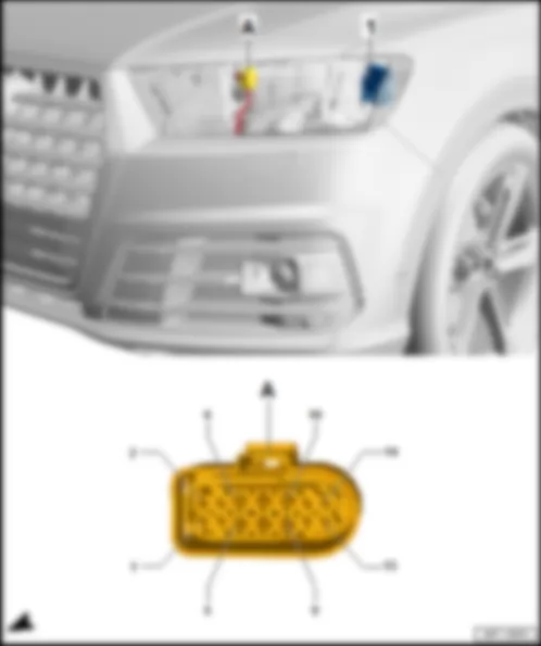
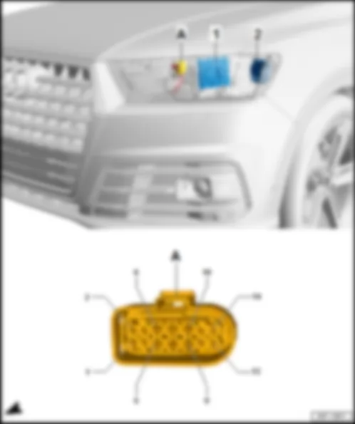
| -T14d- (A) | Designation | | -T14e- (A) | Designation |
| 1 | Extended CAN bus, high, to
B108 Connection 1 (CAN bus extended, high), in main wiring harness
Onboard supply control unit -J519-
Front camera for driver assist systems -R242- | | 1 | Extended CAN bus, high, to
Onboard supply control unit -J519- |
| 2 | Extended CAN bus, low, to
B109 Connection 1 (CAN bus extended, low), in main wiring harness
Onboard supply control unit -J519-
Front camera for driver assist systems -R242- | | 2 | Extended CAN bus, low, to
Onboard supply control unit -J519- |
| 3 | | | 3 | |
| 4 | | | 4 | |
| 5 | Terminal 31, to 376 earth connection 11 in main wiring harness
655 Earth point, on left headlight | | 5 | Terminal 31, to 377 earth connection 12 in main wiring harness
656 Earth point, on right headlight |
| 6 | Onboard supply control unit -J519- | | 6 | Onboard supply control unit -J519- |
| 7 | Terminal 31, to 376 earth connection 11 in main wiring harness
655 Earth point, on left headlight | | 7 | Terminal 31, to 377 earth connection 12 in main wiring harness
656 Earth point, on right headlight |
| 8 | Terminal 15, from fuse carrier 4 -ST4- in fuse holder B -SB- | | 8 | Terminal 15, from fuse carrier 4 -ST4- in fuse holder B -SB- |
| 9 | Onboard supply control unit -J519- | | 9 | Onboard supply control unit -J519- |
| 10 | Terminal 31, to 376 earth connection 11 in main wiring harness
655 Earth point, on left headlight | | 10 | Terminal 31, to 377 earth connection 12 in main wiring harness
656 Earth point, on right headlight |
| 11 | Onboard supply control unit -J519- | | 11 | Onboard supply control unit -J519- |
| 12 | | | 12 | |
| 13 | | | 13 | |
| 14 | | | 14 | |
 Deutsch
 English
 English
 Español
 Français
 Nederlands
 Русский

