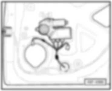
AUDI A4 2005 – Convenience system . Wiring diagrams, Pin Connector, Location – Kopplingsscheman för bilar
AUTOMOTIVE ELECTRICIANS PORTAL
AUDI A4 2005 – Convenience system . Wiring diagrams, Pin Connector, Location
Wiring Diagram AUDI A4 2005 - Fuses https://portal-diagnostov.com/license.html
https://portal-diagnostov.com/license.html
Automotive Electricians Portal FZCO
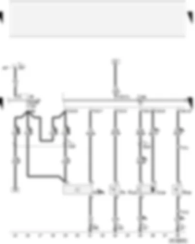
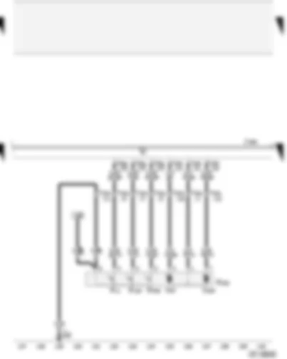
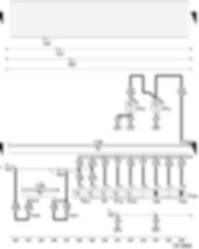
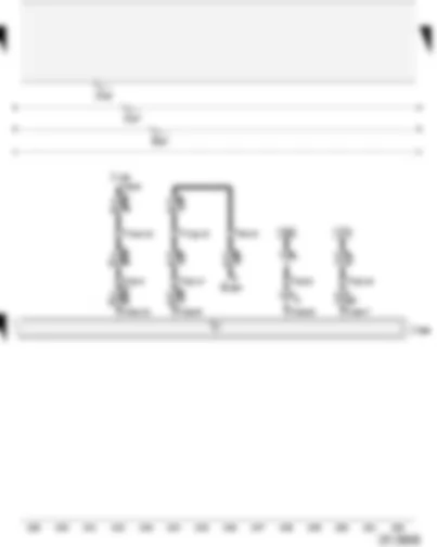
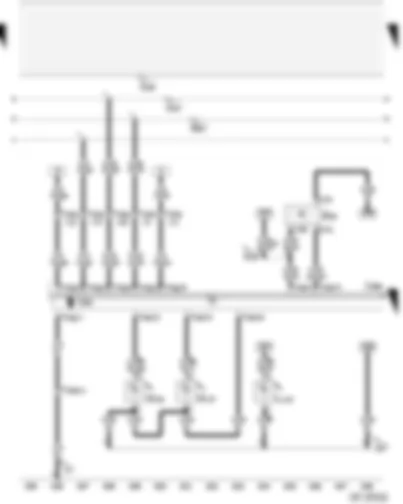
Automotive Electricians Portal FZCO Wiring Diagram AUDI A4 2005 - Handbrake warning switch - rear lid contact switch for anti-theft alarm - alarm horn - rear lid release motor F9 Handbrake warning switch F123 Rear lid contact switch for anti-theft alarm system F248 Release button for rear lid lock cylinder H12 Alarm horn J393 Convenience system central control unit S238 Fuse in fuse holder T4l 4-pin connector, black, in rear lid T12h 12-pin connector, black, on convenience system central control unit (used to be connector 1) T12i 12-pin connector, black, on convenience system central control unit (used to be connector 3) T16i 16-pin connector, brown, on convenience system central control unit (used to be connector 5) V139 Rear lid release motor 87 Earth connection 2, in rear wiring harness 135 Earth connection 2, in dash panel wiring harness 249 Earth connection 2, in interior wiring harness A57 Positive connection 3 (30), in dash panel wiring harness A66 Connection (30a, CL/ATA/IR), in dash panel wiring harness B154 Connection 1 (DCt), in interior wiring harness * for models with anti-theft alarm system only (DWA) and without US equipment ** For Avant models ⇒ see applicable Current Flow Diagram: Avant models, rear *** for models with US equipment only **** for models without US equipment only
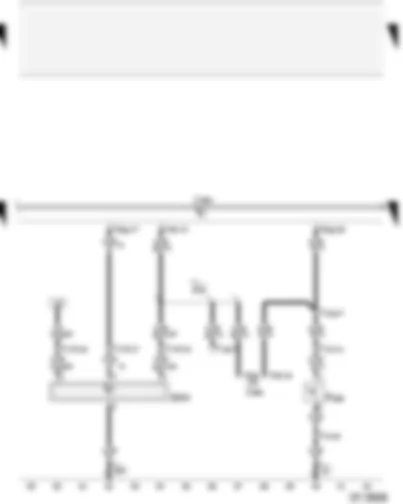
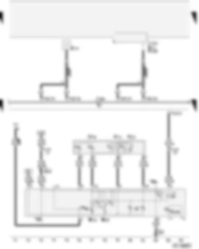
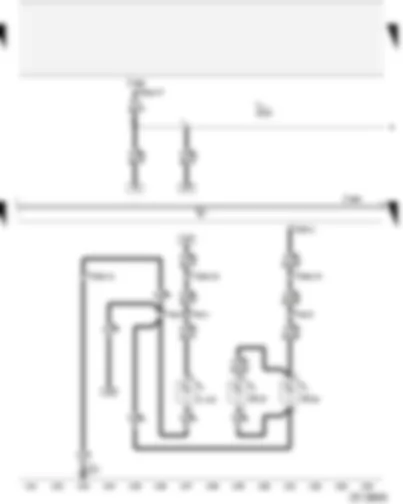
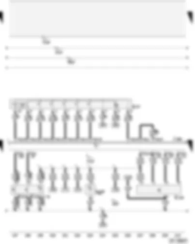
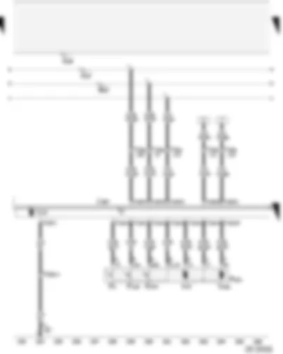
Wiring Diagram AUDI A4 2005 - Convenience system central control unit - bonnet contact switch - interior monitor send and receive module 1 F266 Bonnet contact switch G303 Interior monitor send and receive module 1 J285 Control unit with display in dash panel insert J393 Convenience system central control unit T10d 10-pin connector, grey, coupling station on left of A-pillar T14 14-pin connector, black, on left in engine compartment T16 16-pin connector, black, diagnostic connector T16i 16-pin connector, brown, on convenience system central control unit (used to be connector 5) T17f 17-pin connector, orange, coupling station on left of A-pillar T20g 20-pin connector, red, on convenience system central control unit (used to be connector 4) T32 32-pin connector, blue, on dash panel insert T32a 32-pin connector, green, on dash panel insert 347 Earth connection, in roof wiring harness A76 Connection (diagnosis wire K), in dash panel wiring harness * for models with anti-theft alarm system only (DWA) and without US equipment
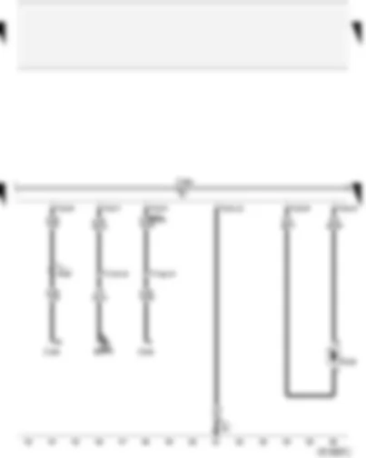
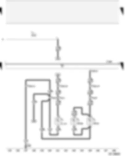
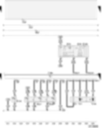
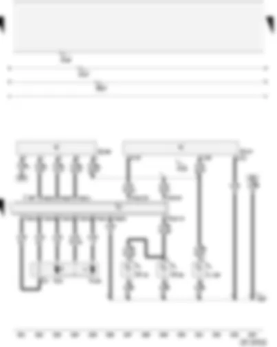
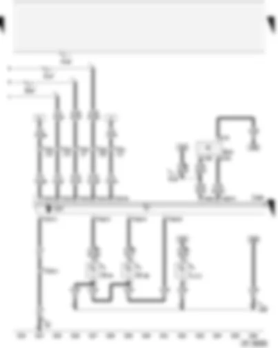
Wiring Diagram AUDI A4 2005 - Convenience system central control unit - tank filler flap locking motor F4 Reversing light switch J234 Airbag control unit J245 Sliding sunroof adjustment control unit J393 Convenience system central control unit T12h 12-pin connector, black, on convenience system central control unit (used to be connector 1) T12i 12-pin connector, black, on convenience system central control unit (used to be connector 3) T17d 17-pin connector, red, coupling station on electronics box, plenum chamber T17g 17-pin connector, dark brown, coupling station on left of A-pillar V155 Tank filler flap locking motor 81 Earth connection 1, in dash panel wiring harness A125 Connection (crash signal), in dash panel wiring harness * for models with 5-speed manual gearbox (not for all engine versions) only ** for models with 6-speed manual gearbox (not for all engine versions) only *** for models with automatic gearbox only, ⇒ applicable Current Flow Diagram: automatic gearbox **** for models with sliding/tilting sunroof
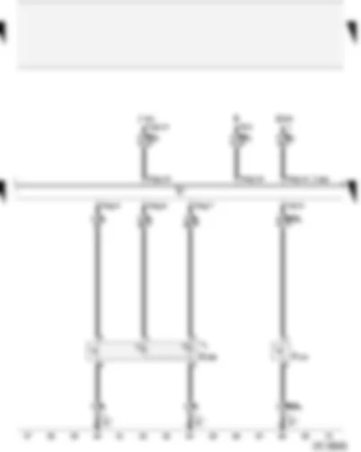
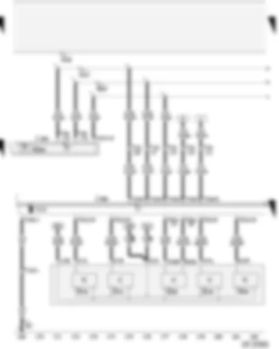
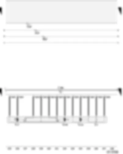
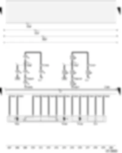
Wiring Diagram AUDI A4 2005 - Rear central switch for interior locking - contact switch in lock cylinder for rear lid - anti-theft alarm system - central locking system E286 Rear central switch for interior locking F124 Contact switch in lock cylinder for rear lid, anti-theft alarm system, central locking system G184 Rear right side window glass breakage sensor J393 Convenience system central control unit J401 Navigation system with CD drive control unit R Radio T8 8-connector, black, radio connector III T16i 16-pin connector, brown, on convenience system central control unit (used to be connector 5) T16j 16-pin connector, black, on navigation system with CD drive control unit, connector D T20g 20-pin connector, red, on convenience system central control unit (used to be connector 4) 81 Earth connection 1, in dash panel wiring harness 87 Earth connection 2, in rear wiring harness * depends on equipment ** For Avant models ⇒ see applicable Current Flow Diagram: Avant models, rear *** Depends on equipment (for ATA only) **** applicable for saloon models
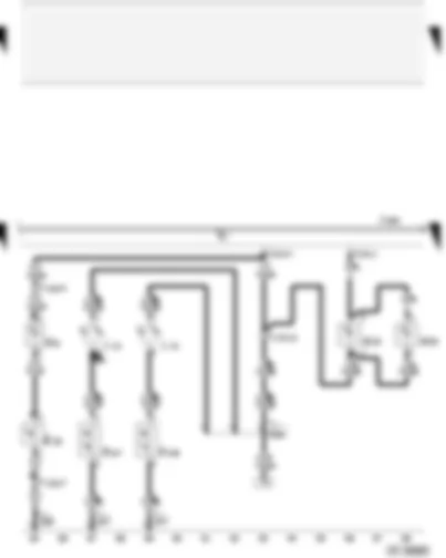
Wiring Diagram AUDI A4 2005 - Convenience system central control unit - interior lights - reading lights - central locking and anti-theft alarm system aerial J393 Convenience system central control unit J515 Aerial selection control unit K145 Front passenger side airbag deactivated warning lamp R11 Aerial R47 Central locking and anti-theft alarm system aerial R108 Left aerial module T12h 12-pin connector, black, on convenience system central control unit (used to be connector 1) T16i 16-pin connector, brown, on convenience system central control unit (used to be connector 5) T17f 17-pin connector, orange, coupling station on left of A-pillar W Front interior light W11 Rear left reading light W12 Rear right reading light W13 Front passenger reading light W19 Reading light/driver side W43 Rear interior light Y7 Automatic anti-dazzle interior mirror 347 Earth connection, in roof wiring harness B270 Connection (58s), in roof wiring harness * for models with automatic headlight switching / surround lighting only ** for models with automatic anti-dazzle interior mirror only *** For models with sliding/tilting sunroof see applicable Current Flow Diagram **** for models without radio only ***** ⇒ applicable Current Flow Diagram for radio / radio-navigation system or avant
Wiring Diagram AUDI A4 2005 - Convenience system central control unit - luggage compartment lights - glove compartment light - vanity mirror light E26 Glove compartment light switch F147 Driver vanity mirror contact switch F148 Front passenger vanity mirror contact switch J393 Convenience system central control unit L31 Vanity mirror light bulb T12d 12-pin connector, brown, near glove compartment T12h 12-pin connector, black, on convenience system central control unit (used to be connector 1) T17f 17-pin connector, orange, coupling station on left of A-pillar W6 Glove compartment light W18 Luggage compartment light on left W35 Right luggage compartment light 238 Earth connection 1, in interior wiring harness 347 Earth connection, in roof wiring harness B250 Positive connection in roof wiring harness * For Avant models ⇒ see applicable Current Flow Diagram: Avant models, rear ** depends on equipment *** ⇒ applicable Current Flow Diagram: garage door operation
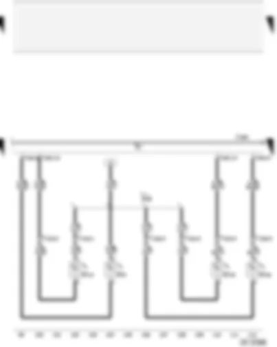
Wiring Diagram AUDI A4 2005 - Convenience system central control unit - footwell lights J393 Convenience system central control unit T10o 10-pin connector, red, coupling station seat wiring, driver seat T10p 10-pin connector, red, coupling station seat wiring, front passenger seat T12d 12-pin connector, brown, near glove compartment T16h 16-pin connector, black, on convenience system central control unit (used to be connector 2) W9 Left footwell light W10 Right footwell light W45 Rear left footwell light W46 Rear right footwell light A29 Connection (interior light), in dash panel wiring harness * for models with 'light equipment' only
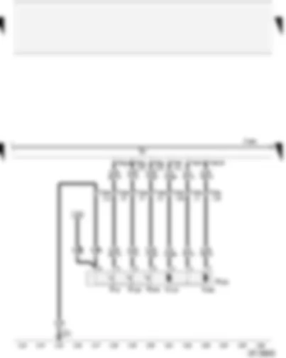
Wiring Diagram AUDI A4 2005 - Convenience system central control unit - rear left central locking lock unit - without rear window regulator F10 Rear left door contact switch F132 Rear left central locking actuator F222 Rear left central locking lock unit F245 Rear left door central locking actuator for deadlock function J393 Convenience system central control unit T16h 16-pin connector, black, on convenience system central control unit (used to be connector 2) T20b 20-pin connector, black, door, B pillar, left T20g 20-pin connector, red, on convenience system central control unit (used to be connector 4) V115 Rear left door central locking motor V163 Rear left door central locking deadlock function motor 277 Earth connection 3, in interior wiring harness * for models without 'light equipment' only ** for models with 'light equipment' only
Wiring Diagram AUDI A4 2005 - Convenience system central control unit - rear right central locking lock unit - without rear window regulator F11 Rear right door contact switch F134 Rear right central locking actuator F223 Rear right central locking lock unit F246 Rear right door central locking actuator for deadlock function J393 Convenience system central control unit T16h 16-pin connector, black, on convenience system central control unit (used to be connector 2) T20c 20-pin connector, black, door, B pillar, right T20g 20-pin connector, red, on convenience system central control unit (used to be connector 4) V97 Rear right door central locking motor V164 Rear right door central deadlock function locking motor 249 Earth connection 2, in interior wiring harness * for models without 'light equipment' only ** for models with 'light equipment' only
Wiring Diagram AUDI A4 2005 - Convenience system central control unit - rear left door illumination - without rear window regulator J285 Control unit with display in dash panel insert J393 Convenience system central control unit L110 Rear left door opener illumination T4p 4-pin connector, black, in rear left door T16h 16-pin connector, black, on convenience system central control unit (used to be connector 2) T20b 20-pin connector, black, door, B pillar, left T32a 32-pin connector, green, on dash panel insert W33 Rear left entry light W37 Rear left door warning lamp 277 Earth connection 3, in interior wiring harness A175 Connection (58s), in dash panel wiring harness * depends on equipment
Wiring Diagram AUDI A4 2005 - Convenience system central control unit - door illumination - without rear window regulator J393 Convenience system central control unit L111 Rear right door opener illumination bulb T4q 4-pin connector, black, in rear right door T16h 16-pin connector, black, on convenience system central control unit (used to be connector 2) T20c 20-pin connector, black, door B-pillar right W34 Rear right entry light W38 Rear right door warning lamp 249 Earth connection 2, in interior wiring harness A175 Connection (58s), in dash panel wiring harness * depends on equipment
Wiring Diagram AUDI A4 2005 - Convenience system central control unit - driver side window regulator control unit - window regulator switch - vehicle inclination sender E39 Rear window regulator isolation switch E40 Front left window regulator switch E41 Front right window regulator switch E53 Rear left window regulator switch, in driver door E55 Rear right window regulator switch, driver G384 Vehicle inclination sender J386 Driver door control unit J393 Convenience system central control unit T10e 10-pin connector, black, on door control unit, driver door T12h 12-pin connector, black, on convenience system central control unit (used to be connector 1) T16i 16-pin connector, brown, on convenience system central control unit (used to be connector 5) T20 20-pin connector, black, door, A pillar, left T32c 32-pin connector, grey, driver door control unit V14 Left window regulator motor A146 Connection (convenience CAN bus, high), in dash panel wiring harness A147 Connection (convenience CAN bus, low), in dash panel wiring harness B207 Connection (convenience), in interior wiring harness * for models without 'light equipment' only ** for models with 'light equipment' only
Wiring Diagram AUDI A4 2005 - Driver side window regulator control unit - driver side central locking lock unit - entry light - driver side door warning lamp F2 Driver door contact switch F131 Front left central locking actuator F220 Driver side central locking lock unit F241 Driver side contact switch in lock cylinder F243 Driver door central locking actuator for deadlock function J386 Driver door control unit J526 Telephone and telematics control unit T12 12-pin connector, black, on door control unit, driver door T20 20-pin connector, black, door, A pillar, left T32c 32-pin connector, grey, driver door control unit T42 42-pin connector, black, on telephone / telematics control unit V56 Driver door central locking motor V161 Driver door central locking deadlock function motor W30 Driver side door warning lamp W31 Front left entry light 205 Earth connection, in driver door wiring harness A146 Connection (convenience CAN bus, high), in dash panel wiring harness A147 Connection (convenience CAN bus, low), in dash panel wiring harness B136 Connection (open - convenience system), in window regulator wiring harness B137 Connection (close - convenience system), in window regulator wiring harness B207 Connection (convenience), in interior wiring harness * for models with US equipment only ** depends on equipment
Wiring Diagram AUDI A4 2005 - Driver side window regulator control unit - driver seat memory operating unit - tank filler flap remote release switch E97 Driver seat memory operating unit E150 Driver side interior locking switch E204 Tank filler flap remote release switch E233 Rear lid remote release button J386 Driver side door control unit L76 Button illumination bulb L108 Driver door opener illumination bulb T32c 32-pin connector, grey, driver side door control unit 205 Earth connection, in driver door wiring harness A146 Connection (convenience CAN bus, high), in dash panel wiring harness A147 Connection (convenience CAN bus, low), in dash panel wiring harness B207 Connection (convenience), in interior wiring harness R52 Connection (58s), in driver side door wiring harness * for models with seat adjustment and memory function only ** depends on equipment *** Country specific **** for models with tank filler flap remote release switch only
Wiring Diagram AUDI A4 2005 - Driver side window regulator control unit - adjustment switch for mirror with fold-in feature - interior monitor deactivation switch E43 Mirror adjustment switch E48 Mirror adjustment change-over switch E168 Adjustment switch for mirror with fold-in feature E183 Interior monitoring deactivation switch E217 Alarm system off switch J386 Driver side door control unit K133 Central locking deadlock function warning lamp T16b 16-pin connector, driver side door control unit T32c 32-pin connector, grey, driver side door control unit V17 Driver side mirror adjustment motor V149 Driver side mirror adjustment motor Z4 Driver side heated exterior mirror 205 Earth connection, in driver door wiring harness A146 Connection (convenience CAN bus, high), in dash panel wiring harness A147 Connection (convenience CAN bus, low), in dash panel wiring harness B207 Connection (convenience), in interior wiring harness * for models with anti-theft alarm system (ATA) only ** for models with interior monitoring switch only
Wiring Diagram AUDI A4 2005 - Driver door control unit - mirror adjustment with fold-in feature J386 Driver door control unit T16b 16-pin connector, driver door control unit V17 Driver side mirror adjustment motor V121 Driver side folding mirror motor V149 Driver side mirror adjustment motor Z4 Driver side heated exterior mirror A146 Connection (convenience CAN bus, high), in dash panel wiring harness A147 Connection (convenience CAN bus, low), in dash panel wiring harness B207 Connection (convenience), in interior wiring harness
Wiring Diagram AUDI A4 2005 - Driver door control unit - garage door operating unit - seat adjustment with memory control unit E284 Garage door operating unit J136 Seat adjustment with memory control unit J386 Driver door control unit T6m 6-pin connector, on the garage door operating unit T10e 10-pin connector, black, on door control unit, driver door T10o 10-pin connector, red, coupling station seat wiring, driver seat T17g 17-pin connector, dark brown, coupling station on left A-pillar T20 20-pin connector, black, door, A pillar, left T32e 32-pin connector, on seat adjustment with memory control unit A146 Connection (convenience CAN bus, high), in dash panel wiring harness A147 Connection (convenience CAN bus, low), in dash panel wiring harness B207 Connection (convenience), in interior wiring harness * for models with automatic anti-dazzle interior mirror only ** for models with garage door operation only *** for models with seat adjustment and memory function only
Wiring Diagram AUDI A4 2005 - Front passenger side window regulator control unit - front passenger side central locking lock unit F3 Front passenger door contact switch F133 Front right central locking actuator F221 Front passenger side central locking lock unit F244 Front passenger door central locking actuator for deadlock function J387 Front passenger door control unit T10f 10-pin connector, black, on door control unit, front passenger door T12a 12-pin connector, black, on door control unit, front passenger door T20a 20-pin connector, black, door, A pillar, right V15 Right window regulator motor V57 Front passenger seat central locking motor V162 Front passenger door central locking deadlock function motor A146 Connection (convenience CAN bus, high), in dash panel wiring harness A147 Connection (convenience CAN bus, low), in dash panel wiring harness B207 Connection (convenience), in interior wiring harness
Wiring Diagram AUDI A4 2005 - Front passenger door control unit - mirror adjustment with fold-in feature - automatic anti-dazzle interior mirror J387 Front passenger door control unit T10f 10-pin connector, black, on door control unit, front passenger door T16c 16-pin connector, front passenger door control unit T17f 17-pin connector, orange, coupling station on left of A-pillar T20a 20-pin connector, black, door, A pillar, right V25 Mirror adjustment motor (front passenger side) V122 Front passenger side folding mirror motor V150 Front passenger side mirror adjustment motor Y7 Automatic anti-dazzle interior mirror Z5 Front passenger side heated exterior mirror A146 Connection (convenience CAN bus, high), in dash panel wiring harness A147 Connection (convenience CAN bus, low), in dash panel wiring harness A187 Connection 1 (automatic anti-dazzle interior mirror), in dash panel wiring harness A188 Connection 2 (automatic anti-dazzle interior mirror), in dash panel wiring harness B207 Connection (convenience), in interior wiring harness * for models with automatic anti-dazzle interior mirror only
Wiring Diagram AUDI A4 2005 - Front passenger side window regulator control unit - right electric exterior mirror - door illumination E107 Window regulator switch, in front passenger door E198 Front passenger side interior locking switch J387 Front passenger door control unit L109 Front passenger side door opener illumination T16c 16-pin connector, front passenger door control unit T32d 32-pin connector, grey, front passenger door control unit V25 Mirror adjustment motor (front passenger side) V150 Front passenger side mirror adjustment motor W32 Front right entry light W36 Front passenger side door warning lamp Z5 Front passenger side heated exterior mirror 206 Earth connection, in front passenger door wiring harness A146 Connection (convenience CAN bus, high), in dash panel wiring harness A147 Connection (convenience CAN bus, low), in dash panel wiring harness B207 Connection (convenience), in interior wiring harness R53 Connection (58s), in front passenger side door wiring harness * depends on equipment
Wiring Diagram AUDI A4 2005 - Rear left door control unit - rear left window regulator - rear left door illumination E52 Rear left window regulator switch (in door) J388 Rear left door control unit L110 Rear left door opener illumination T10g 10-pin connector, black, on rear left door control unit T16d 16-pin connector, brown, rear left door control unit T20b 20-pin connector, black, door, B pillar, left V26 Rear left window regulator motor W33 Rear left entry light W37 Rear left door warning lamp 207 Earth connection, in rear left door wiring harness A146 Connection (convenience CAN bus, high), in dash panel wiring harness A147 Connection (convenience CAN bus, low), in dash panel wiring harness B207 Connection (convenience), in interior wiring harness R54 Connection (58s), in rear left door wiring harness * depends on equipment
Wiring Diagram AUDI A4 2005 - Rear left door control unit - rear left central locking lock unit F10 Rear left door contact switch F132 Rear left central locking actuator F222 Rear left central locking lock unit F245 Rear left door central locking actuator for deadlock function J388 Rear left door control unit T12b 12-pin connector, black, on rear left door control unit V115 Rear left door central locking motor V163 Rear left door central locking deadlock function motor A146 Connection (convenience CAN bus, high), in dash panel wiring harness A147 Connection (convenience CAN bus, low), in dash panel wiring harness B207 Connection (convenience), in interior wiring harness
Wiring Diagram AUDI A4 2005 - Rear right door control unit - rear right window regulator - rear right door illumination E54 Rear right window regulator switch (in door) J389 Rear right door control unit L111 Rear right door opener illumination T10h 10-pin connector, black, on rear right door control unit T16e 16-pin connector, brown, rear right door control unit T20c 20-pin connector, black, door, B pillar, right V27 Rear right window regulator motor W34 Rear right entry light W38 Rear right door warning lamp 208 Earth connection, in rear right door wiring harness A146 Connection (convenience CAN bus, high), in dash panel wiring harness A147 Connection (convenience CAN bus, low), in dash panel wiring harness B207 Connection (convenience), in interior wiring harness R55 Connection (58s), in rear right door wiring harness * depends on equipment
Wiring Diagram AUDI A4 2005 - Rear right door control unit - rear right central locking lock unit F11 Rear right door contact switch F134 Rear right central locking actuator F223 Rear right central locking lock unit F246 Rear right door central locking actuator for deadlock function J389 Rear right door control unit T12c 12-pin connector, black, on rear right door control unit V97 Rear right door central locking motor V164 Rear right door central deadlock function locking motor
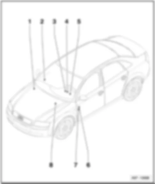
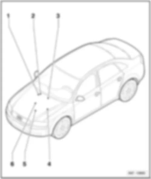
AUDI A4 2005 Overview of fuses q Components: -S126-, -S328-
q Components: -S37-, -S45-, -S87-, -S100-, -S184-, -S280-
q Components: -S42-, -S51-, -S123-, -S214-
q Location up to July 2004
q Location from August 2004
Audi A4 Fitting Locations No. 802 / 2
q Components: -S1- up to -S22- and -S223- up to -S244-
q Location up to July 2004
q Location from August 2004
7 -
q Components: -S55-, -S57-, -S182-, -S183-, -S184-, -S291-, -S292-, -S293-, S294-, -S295-, -S296-, -S297-, -S298-
Audi A4 Fitting Locations No. 802 / 3
q Location for diesel engines, up to July 2004
q Location for engine codes BKE, BRB, BNA, BLB, BRC, BPW, BVG, BVF, BRF, BRE, BVA, BRD
q Location for engine codes BSG, BPP, BTP, BKN, ASB
q Location for engine codes BGB, BPG, BWE, BWT, BUL, BPJ, BYK
q Location for engine code ALZ
q Location for engine code ALT
q Location for engine code BDG
q Location for engine codes BFB, BBK, BHF
q Location for engine code AWA
Audi A4 Fitting Locations No. 802 / 4
t Location for engine codes AUK, BKH
t Location for engine code BNS
t Location for engine code BBJ, with manual gearbox or multitronic
t Location for engine code BBJ with AG5
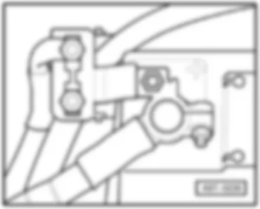
Main fuse
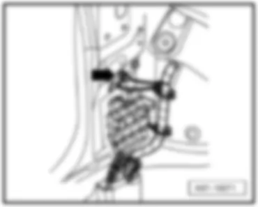
AUDI A4 2005 Position of fuses, coupling station of A-pillar bottom right, behind the trim
E - Seat adjustment fuse -S46-
E - Seat adjustment fuse -S46- (with lumbar support adjustment)
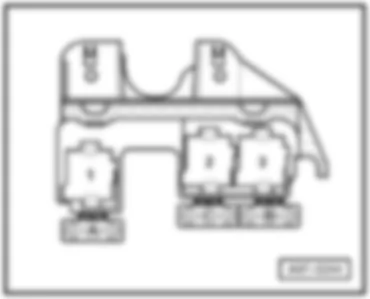
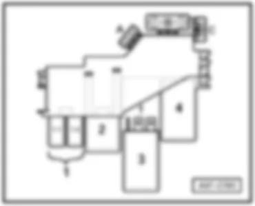
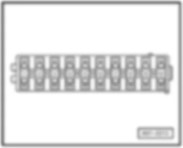
AUDI A4 2005 Position of fuses, relay carrier (3-pin) A ¹) - Auxiliary heater fuse -S62-
B - Auxiliary heater fuse -S126-
C - Auxiliary heater fuse 2 -S328-
¹) applicable up to model year 2003
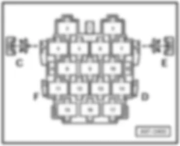
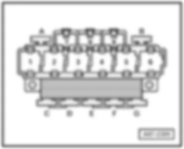
AUDI A4 2005 Position of fuses, relay carrier (9-pin) with onboard supply control unit Driver side dash panel, behind the relay carrier (3-pin)
A - Rear roller blind thermal fuse -S100-
B - Rear roller blind thermal fuse -S100-
B - Socket 1 fuse (driving school vehicle) -S184-
D - Window regulator single fuse 2 -S280-
E - Driver seat adjustment thermal fuse 2 -S45-
F - Window regulator single fuse -S37-
G - Trailer towing attachment thermal fuse -S87-
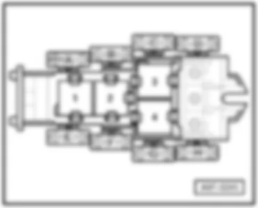
AUDI A4 2005 Position of fuses, relay carrier (4-pin) with screw connection, up to July 2004 B - Optional equipment: vermin repellent
E - Radiator fan run-on fuse -S214-
G - Radiator fan single fuse -S42-
H - ABS control unit fuse 1 -S123-
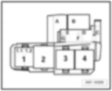
AUDI A4 2005 Position of fuses, relay carrier (4-pin) with screw connection, from August 2004 B - Optional equipment: vermin repellent
E - S51 - Fuse (driving school vehicle) ¹) -S51-
F - Fuse (driving school vehicle) ³) -S51-
- Radiator fan single fuse ¹)²) -S42-
G - Radiator fan run-on fuse¹)²) -S214-
- Radiator fan single fuse ⁴) -S42-
H - ABS control unit fuse 1 -S123-
¹) for engine codes BBK, BHF, BNS only
²) for engine codes BKN, ASB, BPP, BSG, BTP only
³) not for engine codes BBK, BHF
⁴) not for engine codes BKN, ASB, BPP, BSG, BTP, BBK, BHF
AUDI A4 2005 Position of fuses, relay carrier (4-pin), petrol engines, up to July 2004 In electronics box in plenum chamber
A - Engine electronics fuse -S282-
B - Secondary air pump fuse -S130-
C - Automatic gearbox fuse, run-on -S286-
AUDI A4 2005 Position of fuses, relay carrier (4-pin), diesel engines, up to July 2004 In electronics box in plenum chamber
A - Engine control unit fuse -S102-
- Engine electronics fuse -S282-
B - Engine glow plug strip fuse -S39-
C - Automatic gearbox fuse, run-on -S286-
- Engine control unit fuse ²) -S102-
D - Glow plug fuse 2 -S189-
F ¹) - Glow plug fuse 2 -S189-
¹) applicable from model year 2002
²) for models with engine code BKE only
Note:
The positions D and F are in the electronics box.
AUDI A4 2005 Position of fuses, relay carrier (4-pin), engine codes BKE, BRB, BNA, BLB, BRC, BPW, BVG, BVF, BRF, BRE, BVA, BRD, from August 2004 In electronics box in plenum chamber
A - Engine electronics fuse -S282-
B - Engine glow plug strip fuse -S39-
C - Engine control unit fuse -S102-
D - Automatic gearbox fuse, run-on -S286-
E - Engine electronics fuse 2 -S344-
AUDI A4 2005 Position of fuses, relay carrier (4-pin), engine codes BSG, BPP, BTP, BKN, ASB, from August 2004 In electronics box in plenum chamber
A - Engine electronics fuse -S282-
B - Engine glow plug strip fuse -S39-
C - Engine control unit fuse -S102-
D - Automatic gearbox fuse, run-on -S286-
E - Engine electronics fuse 2 -S344-
G - Engine electronics fuse 3 -S345-
AUDI A4 2005 Position of fuses, relay carrier (4-pin), engine codes BGB, BPG, BWE, BWT, BUL, BPJ, BYK, from August 2004 In electronics box in plenum chamber
A - Engine electronics fuse -S282-
B - Engine electronics fuse 3 -S345-
C - Engine control unit fuse -S102-
E - Engine electronics fuse 2 -S344-
G - Automatic gearbox fuse, run-on -S286-
AUDI A4 2005 Position of fuses, relay carrier (4-pin), engine code ALZ, from August 2004 In electronics box in plenum chamber
A - Engine electronics fuse 2 -S344-
B - Secondary air pump fuse -S130-
D - Engine control unit fuse -S102-
G - Engine electronics fuse -S282-
AUDI A4 2005 Position of fuses, relay carrier (4-pin), engine code ALT, from August 2004 In electronics box in plenum chamber
A - Engine electronics fuse 2 -S344-
B - Engine electronics fuse -S282-
C - Automatic gearbox fuse, run-on -S286-
D - Engine control unit fuse -S102-
AUDI A4 2005 Position of fuses, relay carrier (4-pin), engine code BDG, from August 2004 In electronics box in plenum chamber
A - Engine electronics fuse -S282-
B - Engine glow plug strip fuse -S39-
C - Automatic gearbox fuse, run-on -S286-
H¹) - Glow plug fuse 2 -S189-
¹) on the relay carrier underside
AUDI A4 2005 Position of fuses, relay carrier (4-pin), engine codes BFB, BBK, BHF, from August 2004 In electronics box in plenum chamber
A - Engine electronics fuse 2 -S344-
B - Secondary air pump fuse -S130-
C - Automatic gearbox fuse, run-on -S286-
D - Engine control unit fuse -S102-
G - Engine electronics fuse -S282-
H¹) - Heater fuse ²) -S23-
¹) on the relay carrier underside
AUDI A4 2005 Position of fuses, relay carrier (4-pin), engine code AWA, from August 2004 In electronics box in plenum chamber
A - Engine electronics fuse -S282-
B - Engine electronics fuse 2 -S344-
C - Automatic gearbox fuse, run-on -S286-
H ¹) - Engine electronics fuse 3 -S345-
¹) on the relay carrier underside
AUDI A4 2005 Position of fuses, relay carrier (4-pin), engine codes AUK, BKH, from August 2004 In electronics box in plenum chamber
A - Engine electronics fuse 2 -S344-
B - Engine electronics fuse -S282-
C - Engine control unit fuse -S102-
E - Lambda probe heating thermal fuse -S73-
G - Automatic gearbox fuse, run-on -S286-
AUDI A4 2005 Position of fuses, relay carrier (4-pin), engine code BNS, from August 2004 In electronics box in plenum chamber
A - Engine electronics fuse 2 -S344-
B - Engine electronics fuse -S282-
C - Engine control unit fuse -S102-
E - Lambda probe heating thermal fuse -S73-
? - Brake vacuum pump fuse -S283-
H ¹) - Secondary air pump fuse -S130-
¹) on the relay carrier underside
AUDI A4 2005 Position of fuses, relay carrier (4-pin), engine codes BBJ (with manual gearbox or multitronicВ®), from August 2004 In electronics box in plenum chamber
A - Engine electronics fuse 2 ¹) -S344-
B - Secondary air pump fuse ¹) -S130-
C - Automatic gearbox fuse, run-on ¹) -S286-
D - Engine control unit fuse¹) -S102-
E - Injector fuse ¹) -S116-
G - Engine electronics fuse ¹) -S282-
¹) for models with manual gearbox or with automatic gearbox (multitronic®) only
AUDI A4 2005 Position of fuses, relay carrier (4-pin), engine codes BBJ (with AG5), from August 2004 In electronics box in plenum chamber
A - Engine control unit fuse ¹) -S102-
B - Secondary air pump fuse ¹) -S130-
C - Engine electronics fuse ¹) -S282-
D - Engine electronics fuse 2 ¹) -S344-
E - Injector fuse ¹) -S116-
¹) for models with automatic gearbox (AG5) only
AUDI A4 2005 Position of fuses, fuse holder, up to July 2004 Note:
From fuse number 23 upwards the fuses in the fuse holder are designated as 223 in the Current Flow Diagram
Audi A4 Fitting Locations No. 802 / 27
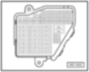
No. Current Flow Diagram designation Nominal value Function/component Terminal 10 - S10 - Fuse in relay plate fuse holder 5 A - E102 - Headlight range control regulator 15 11 - S11 - Fuse in relay plate fuse holder 10 A - J234 - Airbag control unit 15 12 - S12 - Fuse in relay plate fuse holder 10 A - T16 - 16-pin connector, black, diagnostic connector 30 13 - S13 - Fuse in relay plate fuse holder 10 A - J527 - Steering column electronics control unit 30 14 - S14 - Fuse in relay plate fuse holder 10 A - F - Brake light switch 30 15 - S15 - Fuse in relay plate fuse holder 10 A - J285 - Control unit in dash panel insert 30 16 - S16 - Fuse in relay plate fuse holder 5 A - E284 - Garage door operating unit 15 17 - S17 - Fuse in relay plate fuse holder - Vacant 18 - S18 - Fuse in relay plate fuse holder - Vacant
Audi A4 Fitting Locations No. 802 / 29
No. Current Flow Diagram designation Nominal value Function/component Terminal 29 - S229 - Fuse on fuse holder 20 A - N70 - Ignition coil 1 with output stage 87 30 - S230 - Fuse on fuse holder 20 A - J245 - Sliding sunroof adjustment control unit 30 31 - S231 - Fuse on fuse holder 15 A - F125 - Multifunction switch 15 32 - S232 - Fuse on fuse holder 20 A - J583 - NOx sensor control unit 87 33 - S233 - Fuse on fuse holder 15 A - U1 - Cigarette lighter 30
Audi A4 Fitting Locations No. 802 / 31
No. Current Flow Diagram designation Nominal value Function/component Terminal 40 - S240 - Fuse on fuse holder 25 A - H2 - Treble tone horn 30 41 - S241 - Fuse on fuse holder 30 A - J364 - Auxiliary heater control unit 30 42 - S242 - Fuse on fuse holder 25 A - J104 - ABS control unit 30 43 - S243 - Fuse on fuse holder 15 A - J220 - Motronic control unit 15 44 - S244 - Fuse on fuse holder 30 A - E87 - Operating and display unit for air conditioning system/Climatronic 30
AUDI A4 2005 Position of fuses, fuse holder, from August 2004 Note:
From fuse number 23 upwards the fuses in the fuse holder are designated as 223 in the Current Flow Diagram
Audi A4 Fitting Locations No. 802 / 34
No. Current Flow Diagram designation Nominal value Function/component Terminal 10 - S10 - Fuse in relay plate fuse holder 5 A - E102 - Headlight range control regulator 15 11 - S11 - Fuse in relay plate fuse holder 10 A - J234 - Airbag control unit 15 12 - S12 - Fuse in relay plate fuse holder 10 A - T16 - 16-pin connector, black, diagnostic connector 30 13 - S13 - Fuse in relay plate fuse holder 10 A - J527 - Steering column electronics control unit 30 14 - S14 - Fuse in relay plate fuse holder 10 A - F - Brake light switch 30 15 - S15 - Fuse in relay plate fuse holder 10 A - J285 - Control unit in dash panel insert 30 16 - S16 - Fuse in relay plate fuse holder 5 A - E284 - Garage door operating unit 15 17 - S17 - Fuse in relay plate fuse holder 10 A - G397 - Rain and light detector sensor 30 18 - S18 - Fuse in relay plate fuse holder 5 A - V318 - Left dynamic cornering light control motor 15
Audi A4 Fitting Locations No. 802 / 36
No. Current Flow Diagram designation Nominal value Function/component Terminal 29 - S229 - Fuse on fuse holder - Vacant 30 - S230 - Fuse on fuse holder 20 A - J245 - Sliding sunroof adjustment control unit 30 31 - S231 - Fuse on fuse holder 15 A - F4 - Reversing light switch 15 32 - S232 - Fuse on fuse holder 15 A - U10-Trailer socket ²) 75x 33 - S233 - Fuse on fuse holder 15 A - U1 - Cigarette lighter 30 34 - S234 - Fuse on fuse holder 30 A - U5 - 12 V socket 30 35 - S235 - Fuse on fuse holder 30 A - U - socket 30 36 - S236 - Fuse on fuse holder 30 A - J519 - Onboard power supply control unit 75x 37 - S237 - Fuse on fuse holder 30 A - J519 - Onboard power supply control unit 75x
Notes:
t ¹) applicable from February 2005
t ²) applicable from model year 2006
Audi A4 Fitting Locations No. 802 / 38
AUDI A4 2005 Position of fuses, fuse holder for special vehicle - taxi
1 - Taxi meter and alarm system fuse -S183-
2 - Alarm system fuse -S57-
3 - Taxi meter fuse -S182-
9 - Two-way radio fuse -S55-
10 - Socket 1 fuse -S184-
¹) applicable from model year 2006
AUDI A4 2005 Position of fuses, fuse holder for special vehicle - police 1 - Special vehicle fuse 1 -S291-
2 - Special vehicle fuse 2 -S292-
3 - Special vehicle fuse 3 -S293-
4 - Special vehicle fuse 4 -S294-
5 - Special vehicle fuse 5 -S295-
6 - Special vehicle fuse 6 -S296-
7 - Special vehicle fuse 7 -S297-
8 - Special vehicle fuse 8 -S298-
¹) applicable from February 2005
²) applicable from model year 2006
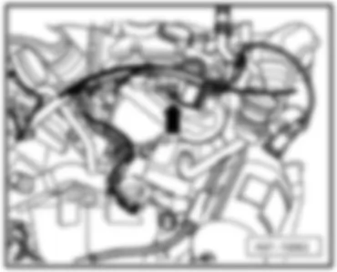
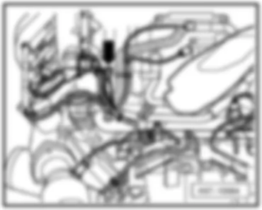
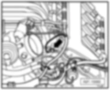
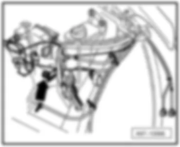
AUDI A4 2005 AUDI A4 2005 Overview of earth points in engine compartment q only for 2.0 l FSI motor, location
q only for 2,5 l engine TDI, location
q only for 2.0 l FSI motor, location
q only for 3.0 l engine, location
Audi A4 Fitting Locations No. 801 / 3
Note:
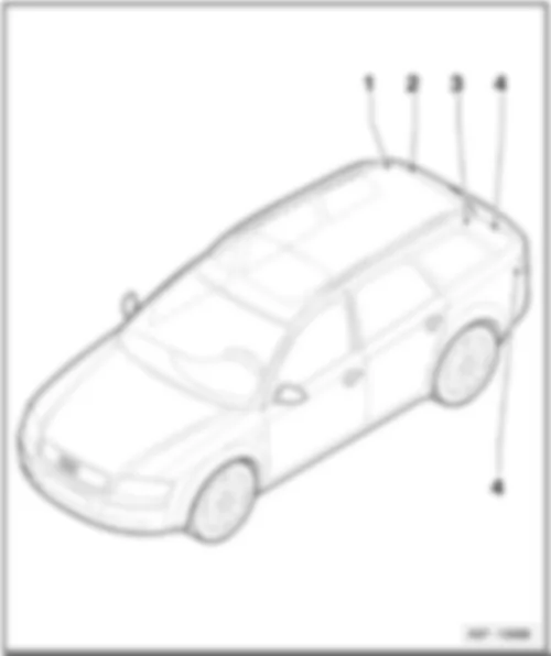
♦ Overview of luggage compartment - Avant models
1 - Earth point, right D-pillar -654-
3 - Earth point, left D-pillar -653-
5 - Earth point, on left in luggage compartment -50-
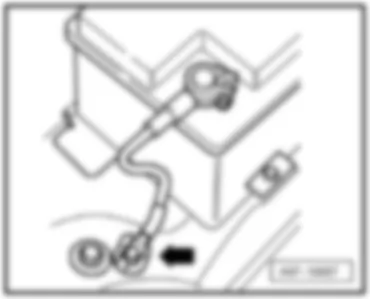
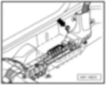
AUDI A4 2005 Earth point, in engine compartment 11 Earth point, in battery box -arrow-
12 Earth point, in engine compartment, left -arrow-
12 Earth point, in engine compartment, left -arrow-
only for 2,0 l engine FSI
12 Earth point, in engine compartment, left -arrow-
only for 2,5 l engine TDI
18 Earth point on engine block -arrow-
18 Earth point on engine block -arrow-
18 Earth point on engine block -arrow-
only for 2,0 l engine FSI
18 Earth point on engine block -arrow-
19 Earth point, near coil -arrow-
26 Earth point, on front apron -arrow-
624 Earth point, starter battery -arrow-
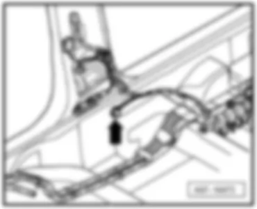
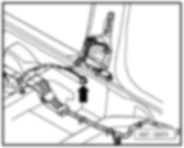
AUDI A4 2005 Earth points, in interior 32 Earth point behind dash panel on left -arrow-
33 Earth point behind dash panel on right -arrow-
43 Earth point, lower part of right A-pillar -arrow-
44 Earth point, lower part of left A-pillar -arrow-
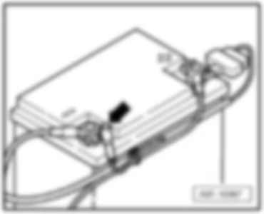
49 Earth point, near convenience system central control unit -arrow-
77 Earth point, lower part of left B-pillar -arrow-
78 Earth point, lower part of right B-pillar -arrow-
610 Earth point (audio), under centre console, front -arrow-
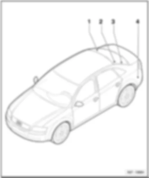
AUDI A4 2005 Earth point, in luggage compartment - saloon models
50 Earth point, on left in luggage compartment -arrow-
653 Earth point, left D-pillar -arrow-
654 Earth point, right D-pillar -arrow-
701 Earth point, in luggage compartment -arrow-
Earth point, in luggage compartment - Avant models 50 Earth point, on left in luggage compartment -arrow-
52 Earth point, on left in rear lid -arrow-
53 Earth point, on right in rear lid -arrow-
653 Earth point, left D-pillar -arrow-
654 Earth point, right D-pillar -arrow-
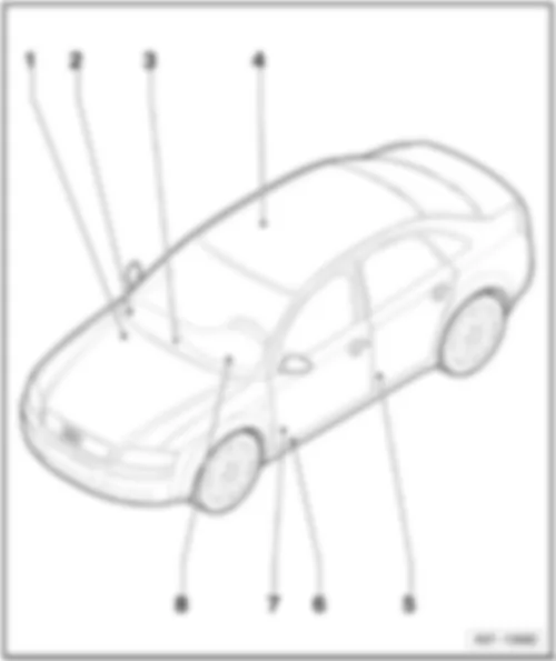
AUDI A4 2005 Control units overview
Audi A4 Fitting Locations No. 804 / 2
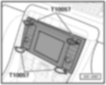
q Location for navigation system RNS-E
Audi A4 Fitting Locations No. 804 / 3
Diesel direct injection system control unit -J248-
17 - Automatic gearbox control unit -J217-
q for models with multitronic® only
AUDI A4 2005 Motronic control unit -J220-, diesel direct injection system control unit -J248-, Simos control unit -J361- On electronics box in plenum chamber
AUDI A4 2005 Automatic gearbox control unit -J217- not for models with multitronic®
In electronics box in plenum chamber
for models with multitronic® only
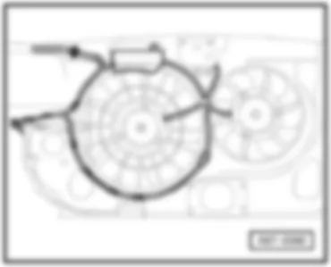
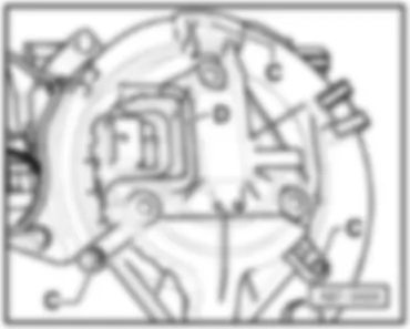
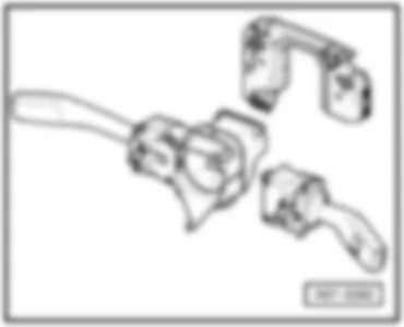
AUDI A4 2005 ABS control unit -J104- AUDI A4 2005 Radiator fan control unit -J293- AUDI A4 2005 Fresh air blower control unit -J126- AUDI A4 2005 Headlight range control, control unit -J431- AUDI A4 2005 Steering column electronics control unit -J527- AUDI A4 2005 Display control unit in dash panel insert -J285- In the dash panel behind the display unit
AUDI A4 2005 Airbag control unit -J234- AUDI A4 2005 Onboard power supply control unit -J519- Behind driver's storage compartment
AUDI A4 2005 Trailer detector control unit -J345- AUDI A4 2005 Parking aid control unit -J446- In left luggage compartment, behind side trim, on apron
AUDI A4 2005 Navigation operating electronics control unit -J402- for navigation system RNS-D only
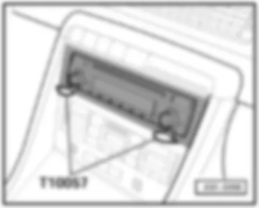
AUDI A4 2005 Radio -R-
not for navigation system
AUDI A4 2005 Navigation system with CD drive control unit -J401- For navigation system NS-Low only
For navigation system RNS-E only
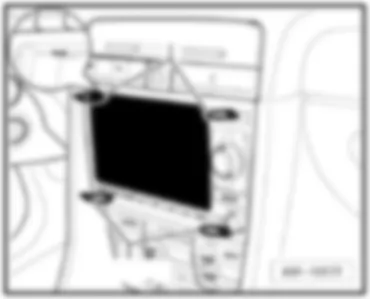
AUDI A4 2005 Control unit with display for radio and navigation system -J503- for navigation system RNS-Low only
AUDI A4 2005 CD changer -R41-
AUDI A4 2005 Telephone and telematics control unit, telematics -J526- For models with telematics only
in electronics box under front passenger seat
AUDI A4 2005 Language input control unit -J507-
For models with telematics only
in electronics box under front passenger seat
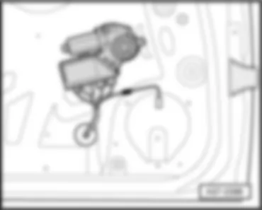
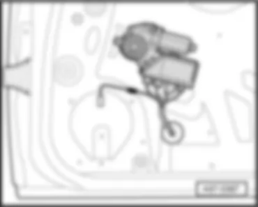
AUDI A4 2005 Convenience system central control unit -J393- AUDI A4 2005 Driver door control unit -J386- AUDI A4 2005 Front passenger side door control unit -J387- In window regulator motor integrated
AUDI A4 2005 Control units overview AUDI A4 2005 Parking aid control unit -J446- In left luggage compartment, behind side trim, on apron
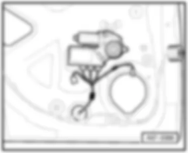
AUDI A4 2005 Rear left door control unit -J388- AUDI A4 2005 Rear right door control unit -J389- In window regulator motor integrated
We use cookies on our website to give you the most relevant experience by remembering your preferences and repeat visits. By clicking “Accept All”, you consent to the use of ALL the cookies. However, you may visit "Cookie Settings" to provide a controlled consent.
Manage consent

 Deutsch
 English
 English
 Español
 Français
 Nederlands
 Русский

