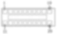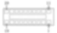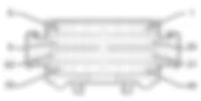

WIRING DIAGRAM - RADIO - Alfa Romeo 159 2.4 JTD 20V Fino a 12/05
COMPONENTS - RADIO - Alfa Romeo 159 2.4 JTD 20V Fino a 12/05
| Component code | Description | Reference to the operation |
| B001 | JUNCTION UNIT | |
| B002 | JUNCTION UNIT UNDER DASHBOARD | |
| B099 | MAXIFUSE BOX ON BATTERY | |
| C020 | PASSENGER SIDE DASHBOARD EARTH | - |
| D001 | FRONT/DASHBOARD COUPLING | - |
| D020 | DASHBOARD/REAR COUPLING | - |
| D030 | DRIVER'S FRONT DOOR COUPLING | - |
| D031 | PASSENGER FRONT DOOR COUPLING | - |
| D035 | LEFT REAR DOOR COUPLING | - |
| D036 | RIGHT REAR DOOR COUPLING | - |
| D047 | CLOCK SPRING COUPLING | - |
| D096 | CD CHANGER CABLE INTERMEDIATE COUPLING | - |
| M001 | BODY COMPUTER | |
| M089 | STEERING LOCK CONTROL UNIT (NBS) | |
| P020 | RADIO | - |
| 5580P12 | CONNECT PANEL REPLACE | |
| 5570T27 | AERIAL SUPPORT - R.R | |
| 5570T96 | REAR SIDE SPEAKER (ONE), LEFT OR RIGHT- R.R | |
| 5570T96 | REAR SIDE SPEAKER (ONE), LEFT OR RIGHT- R.R | |
| 5570T90 | FRONT SPEAKER (ONE), LEFT OR RIGHT - R.R | |
| 5570T90 | FRONT SPEAKER (ONE), LEFT OR RIGHT - R.R | |
| 5570T92 | FRONT TWEETER (ONE), LEFT OR RIGHT - R.R | |
| 5570T92 | FRONT TWEETER (ONE), LEFT OR RIGHT - R.R | |
| 5570T94 | REAR TWEETER (ONE), LH OR RH - R R | |
| Op.5570T94TWEETER POSTERIORE (UNO), SX O DX - S.R.VedereP075MODULO CD CHANGER | - |
COMPONENT LOCATION - RADIO - Alfa Romeo 159 2.4 JTD 20V Fino a 12/05
DESCRIPTION - RADIO - Alfa Romeo 159 2.4 JTD 20V Fino a 12/05
The vehicle is equipped with a radio system comprising:- radio;- front speakers (woofers in the doors and tweeters in the dashboard);- rear speakers located in the doors- cables connecting the radio with the speakers;- aerial with support fitted at the rear of the roof with a coaxial connecting cable.A sophisticated Bose HIFI system with special HIFI speakers and an outside amplifier can also be fitted.
FUNCTIONAL DESCRIPTION - RADIO - Alfa Romeo 159 2.4 JTD 20V Fino a 12/05
Radio P20 is supplied directly (7 of connector A) from the battery via the line of fuse F23 of the engine compartment junction unit B1 .The radio P20 receives an ignition-operated (INT) power supply (pin 4 of connector A) via the line for fuse F49 of the junction unit under the dashboard B2 .Pin 8 of connector A is earthed.Pins 1 and 3 of connector A receive the CAN line by which the radio P20 is connected to the Body Computer M1 and the other system nodes.The radio P20 is connected, via the CAN, to the radio controls on the steering wheel, via the clock spring D47.The following cables with signals for the speakers leave connector B of P20:- pins 5 and 6 to the left front speakers P35 and P45;- pins 3 and 4 to the right front speakers P36 and P46;- pins 7 and 8 to the left rear speakers P30 and P47;- pins 1 and 2 to the right rear speakers P31 and P48;The aerial P25 is connected to the radio by means of the special coaxial cable.A connection lead runs from connector E of P20 to CD player P75:. this cable, is divided into two sections: one under the dashboard and one under the passenger compartment lining (coupling D96).
 Deutsch
 English
 English
 Español
 Français
 Nederlands
 Русский


