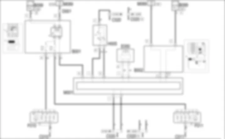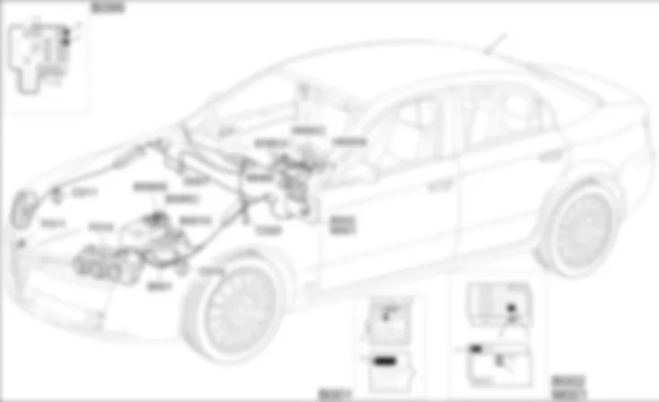

WIRING DIAGRAM - MAIN BEAM HEADLAMPS - Alfa Romeo 159 1.9 JTD 8V Da 01/06
COMPONENTS - MAIN BEAM HEADLAMPS - Alfa Romeo 159 1.9 JTD 8V Da 01/06
| Component code | Description | Reference to the operation |
| B001 | JUNCTION UNIT | |
| B002 | JUNCTION UNIT UNDER DASHBOARD | |
| B099 | MAXIFUSE BOX ON BATTERY | |
| C010 | LEFT FRONT EARTH | - |
| C011 | RIGHT FRONT EARTH | - |
| C020 | PASSENGER SIDE DASHBOARD EARTH | - |
| D001 | FRONT/DASHBOARD COUPLING | - |
| E050 | INSTRUMENT PANEL | |
| F010 | LEFT HEADLAMP | |
| F011 | RIGHT HEADLAMP | |
| H005 | STEERING COLUMN SWITCH UNIT | |
| M001 | BODY COMPUTER | |
| M089 | STEERING LOCK CONTROL UNIT (NBS) |
COMPONENT LOCATION - MAIN BEAM HEADLAMPS - Alfa Romeo 159 1.9 JTD 8V Da 01/06
| Component code | Description | Reference to the operation |
| B001 | JUNCTION UNIT | |
| B002 | JUNCTION UNIT UNDER DASHBOARD | |
| B099 | MAXIFUSE BOX ON BATTERY | |
| C010 | LEFT FRONT EARTH | - |
| C011 | RIGHT FRONT EARTH | - |
| C020 | PASSENGER SIDE DASHBOARD EARTH | - |
| D001 | FRONT/DASHBOARD COUPLING | - |
| E050 | INSTRUMENT PANEL | |
| F010 | LEFT HEADLAMP | |
| F011 | RIGHT HEADLAMP | |
| H005 | STEERING COLUMN SWITCH UNIT | |
| M001 | BODY COMPUTER | |
| M089 | STEERING LOCK CONTROL UNIT (NBS) |
DESCRIPTION - MAIN BEAM HEADLAMPS - Alfa Romeo 159 1.9 JTD 8V Da 01/06
The vehicle is equipped with two high beams in the headlamps.The main beams are switched on by the steering column switch unit:- with the dipped beams on, by pushing the lever towards the dashboard (stable mode)- in flashing mode, by pulling the lever toward the steering wheel (unstable mode)The low beam activation relay is controlled by the Body Computer relay energizing is activated by enablement signals with the TEG inserted (INT) and from the specific signal from the steering column switch unit.Activation/deactivation information is sent via the CAN network: in this way, the main beam warning light is activated in the instrument panel.
FUNCTIONAL DESCRIPTION - MAIN BEAM HEADLAMPS - Alfa Romeo 159 1.9 JTD 8V Da 01/06
The dipped headlamps (earth) activation signal (stable mode) is sent to pin 4 of connector I of the Body Computer M1 from the steering column switch unit H5; the flasher activation (earth) signal (unstable mode) is, on the other hand, sent to pin 33 of connector G of the Body Computer M1.The Body Computer M1 controls the supply for the dipped headlamps sending an earth signal to relay T2 in the junction unit in the engine compartment B1 from pin 9 of connector A of M1 which energizes relay T2: this supplies the dipped headlamps F10 (left) and F11 (right). Each circuit is protected by a fuse in the junction unit B1 : F15 for the left headlamp and F14 for the right.The Body Computer M1 is connected via the CAN line to the instrument panel E50 to manage the "main beam headlamps" warning light.
 Deutsch
 English
 English
 Español
 Français
 Nederlands
 Русский

