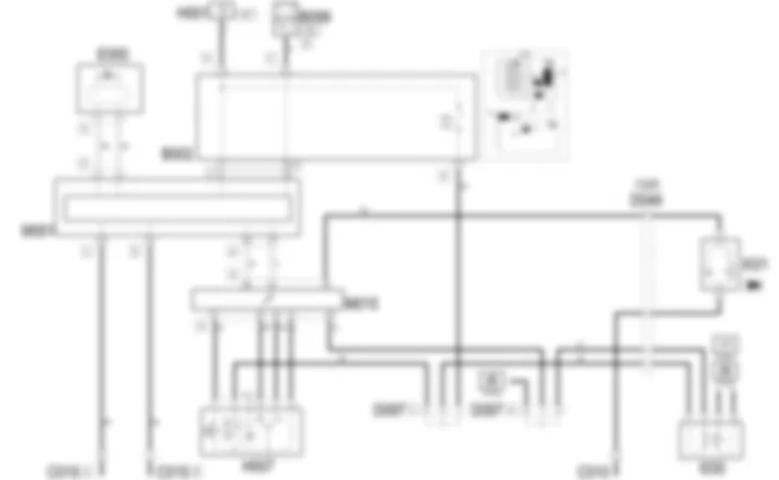
Wiring diagram - CRUISE CONTROL - Alfa Romeo GT 2.0 JTS
Components - CRUISE CONTROL - Alfa Romeo GT 2.0 JTS
| Component code | Description | Reference to the assembly |
| B1 | JUNCTION UNIT | - |
| B2 | JUNCTION UNIT UNDER DASHBOARD | |
| B5 | MAXI FUSE-1 BOX | - |
| B99 | MAXIFUSE BOX ON BATTERY | |
| C15 | FACIA EARTH, DRIVER''S SIDE | - |
| D49 | PEDAL ASSEMBLY JOIN | - |
| D97 | SHORT CIRCUITING COUPLING | - |
| E50 | INSTRUMENT PANEL | |
| H1 | IGNITION SWITCH | |
| H7 | CRUISE CONTROL ( FRONT ) | |
| I30 | BRAKE PEDAL SWITCH ( FRONT ) | |
| I31 | CLUTCH PEDAL SWITCH ( FRONT ) | 1056B |
| I31 | CLUTCH PEDAL SWITCH ( FRONT ) | 1060G |
| M1 | BODY COMPUTER | |
| M10 | ENGINE MANAGEMENT ECU | 1056B |
| M10 | ENGINE MANAGEMENT ECU | 1060G |
Component location - CRUISE CONTROL - Alfa Romeo GT 2.0 JTS
Components - CRUISE CONTROL - Alfa Romeo GT 2.0 JTS
| Component code | Description | Reference to the assembly |
| B1 | JUNCTION UNIT | - |
| B2 | JUNCTION UNIT UNDER DASHBOARD | |
| B5 | MAXI FUSE-1 BOX | - |
| B99 | MAXIFUSE BOX ON BATTERY | |
| C15 | FACIA EARTH, DRIVER''S SIDE | - |
| D49 | PEDAL ASSEMBLY JOIN | - |
| D97 | SHORT CIRCUITING COUPLING | - |
| E50 | INSTRUMENT PANEL | |
| H1 | IGNITION SWITCH | |
| H7 | CRUISE CONTROL ( FRONT ) | |
| I30 | BRAKE PEDAL SWITCH ( FRONT ) | |
| I31 | CLUTCH PEDAL SWITCH ( FRONT ) | 1056B |
| I31 | CLUTCH PEDAL SWITCH ( FRONT ) | 1060G |
| M1 | BODY COMPUTER | |
| M10 | ENGINE MANAGEMENT ECU | 1056B |
| M10 | ENGINE MANAGEMENT ECU | 1060G |
Description - CRUISE CONTROL - Alfa Romeo GT 2.0 JTS
The Cruise Control function - constant speed governor - allows the driver to drive the car at a constant speed without pressing the accelerator pedal.The function is managed by the engine control unit. This receives commands from a Cruise Control lever on the left of the steering wheel beneath the stalk switch unit.The function is engaged by turning the wheel (ON).When a speed is set ( SET + , SET - ), the setting is saved and may be called up at any time ( RCL ).
Functional description - CRUISE CONTROL - Alfa Romeo GT 2.0 JTS
The Cruise Control function is managed by the engine management control unit M10when controlled by the special Cruise Control system control H7located to the left of the steering wheel.The control H7receives an ignition-controlled power supply (INT) pin 2 from the line protected by fuse F35 of the junction unit under the dashboard B2.Control H7 at pin 41 of connector A, with the ON/OFF signal at pin 21 of connector A, with the RCL signal at pin 44 of connector A, with the SET+ signal at pin 43 of connector A, with the SET- signalPin 20 of connector A of M10receives the "pedal released" signal (N.C. contact) coming from the second contact of the brake lights switch I30with an ignition-controlled power supply (INT) from the line protected by fuse F35 of the junction unit under the dashboard B2.Pin 23 of connector A of M10receives the signal coming from the clutch switch I31Via the CAN line the engine management control unit M10is connected to the Body Computer M1and to the instrument panel E50to manage the "Cruise Control on" warning light.
 Deutsch
 English
 English
 Español
 Français
 Nederlands
 Русский

